④ X110
EMERGENCY STOP button / enabling button of the handheld unit
EMERGENCY STOP button already pre-wired to S113
⑤ Pok
Port1
Port2
Port3
Status LED Power OK APCB HT
Status LED X120, green = link, yellow = trac
Status LED X121, green = link, yellow = trac
Status LED XS12, green = link, yellow = trac
⑥ X111 Inputs for EMERGENCY STOP and EMERGENCY STOP override
Already pre-wired to S13 and S113
⑦ X120 / X121 Ethernet ports
⑧ S301
S302
Rotary coding switch for box ID (higher-value bits)
Rotary coding switch for box ID (lower-value bits)
⑨ X32 Interface for rapid traverse override rotary switch
⑩ X130 Optional customer keys
⑪ X170 Power supply of the COM board
Already pre-wired with X10
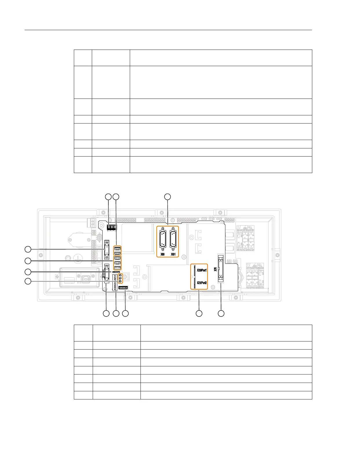
COM board
① X10 24 V power supply (already pre-wired to HT board)
Power supply of the MPP 1500D/E via X100
② X53 / X54 Customer keys, outputs for illuminated keys
③ X60 / X61 Connections for 2 handwheels
④ X70 Direct key connection
⑤ X20 / X21 Ethernet ports
⑥ X50
⑦ S2 DIP switches: MCP address
⑧ X30 Interface for feedrate override rotary switch
Description
3.4 Interfaces
Machine Push Button Panel: MPP 1500D / MPP 1500E
24 Equipment Manual, 04/2021, A5E50753610B AA