SIPART DR19
88 C73000-B7474-C140-06
Program Controller Quick Reference
Via front panel: Int
∧ A (start position, t=0 1. interval)
Via control signal: tS
(acts static, configuring switch S28)
S90=0: Time is stored. Program continues seamlessly with the stored values, if
operating conditions permit.
S90=1: start position (reset state)
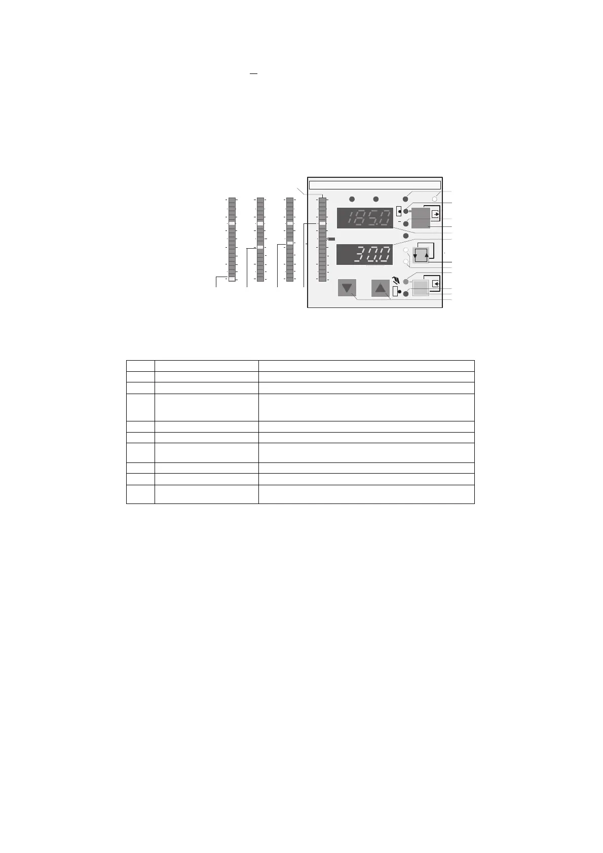
5.2 Operating Example
S1 = 5 S43 = 2 S87 = 1, 2, 3, 5 S88 = 7
(1) Digital display PV-X Remaining time in interval (unit CLFo)
(2) Digital display Sp-W w
pz
display (program target setpoint)
(3) Analog display Program sequence status, 2 segments per interval
(4,5) Signal lamps x,w w permanent light: setpoint w displayed in (2)
w and x flashing: target setpoint w
pz
displayd in (2),
Time left in interval displayd in (1)
(6) Switchover button SP-W display (2) and PV-X display (1)
(7), (8) Adjust setpoint w
i
Decrease/increase setpoint
(9) Switchover button H/A The clock is stopped in manual mode. The Int
∧ H logic
operation resets the program.
(10) Signal lamp External y mode, clock stopped
(11) Signal lamp Manual mode, clock stopped
(13) Switchover button internal/
external setpoint
With Int the clock is stopped. Cold start after "hold" function
by switching to "ext". The program is reset by Int
∧ H.
Reset
Behaviour on
power
supply failure
Configuring
SIPART DR19
SIEMENS
OUT-Y
C
x
w
ADAPT
123
4
SP-W
PV-
X
SIPART DR19
0
3
70
17
15
14
13
1
2
6
4, 5
11
10
9
7, 8
45
100
0
70
40
100
0
100
80
0
20
40
60
100
0
70
ABCD
A flashing: start position
B 2nd half 4th interval, or flashing: hold function
C 1st half 5th interval
D 2nd half 7th interval or program finish
program finish
 Loading...


