SIPART DR19
90 C73000-B7474-C140-06
Program Controller Quick Reference
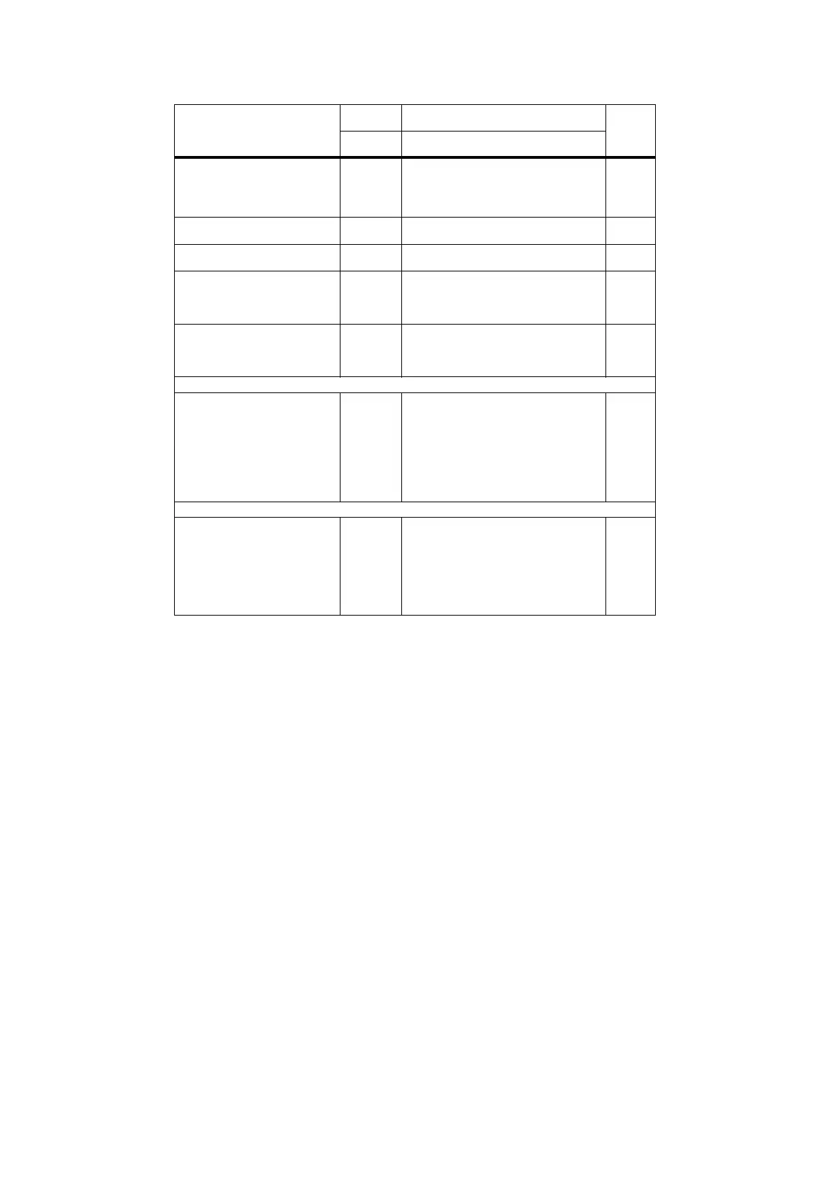
CLPA - Clock parameter list
Parameter/function Indicator
SP-W
Indicator PV-X
Factory
setting
Param.
name
Parameter setting
Program selection PrSE P1 only program 1
P2 only program 2
P1.P2 P1 or P2 Switchover via signal
PU (DI)
CASC P1 and P2 cascaded
P1
Comparison at end of interval
with stop function
Hold oFF, 0,1 ...10
[given% of dA, dE]
oFF
Clock format CLFo h.’ Hrs, Min
’." Min, Sec
h . ’
Time intervals,
Program 1 (10 intervals)
t.01.1
to t.10.1
00.00 to 23.59 or
00.00 to 59.59
00.00
Time intervals,
Program 2 (5 intervals)
t.01.2
to t.05,2
00.00 to 23.59 or
00.00 to 59.59
00.00
Analog values at end of interval
in program 1
A.01.1
to A.10.1
-10% to +110%
of dA, dE, nop
0.0
Analog values at end of interval
in program 2
A.01.2
to A.05.2
-10% to +110%
of dA, dE, nop
0.0
Program 1
Digital output signal Clb1 during
intervals 1 to 10
1.01.1
to
1.10.1
1.PE.1
Lo/Hi
x.PE.x status of the digital outputs at the
end of the program and at the start of the
program in the start position.
Lo
to
Digital output signal Clb6 during
intervals 1 to 10
to
6.01.1
to
6.10.1
6.PE.1
Lo/Hi
x.PE.x status of the digital outputs at the
end of the program and at the start of the
program in the start position.
Lo
Program 2
Digital output signal Clb1 during
intervals 1 to 5.
1.01.2
to
1.05.2,
1.PE.2
Lo/Hi
x.PE.x status of the digital outputs at the
end of the program and at the start of the
program in the start position.
Lo
to
Digital output signal Clb6 during
intervals 1 to 5.
to
6.01.2 to
6.05.2,
6.PE.2
Lo/Hi
x.PE.x status of the digital outputs at the
end of the program and at the start of the
program in the start position.
Lo
 Loading...


