Manual
2 Installation
2.2 Electrical Connection
2.2.2 Wiring of the standard Controller
SIP ART DR24 6DR2410
C79000-G7476-C153-03
113
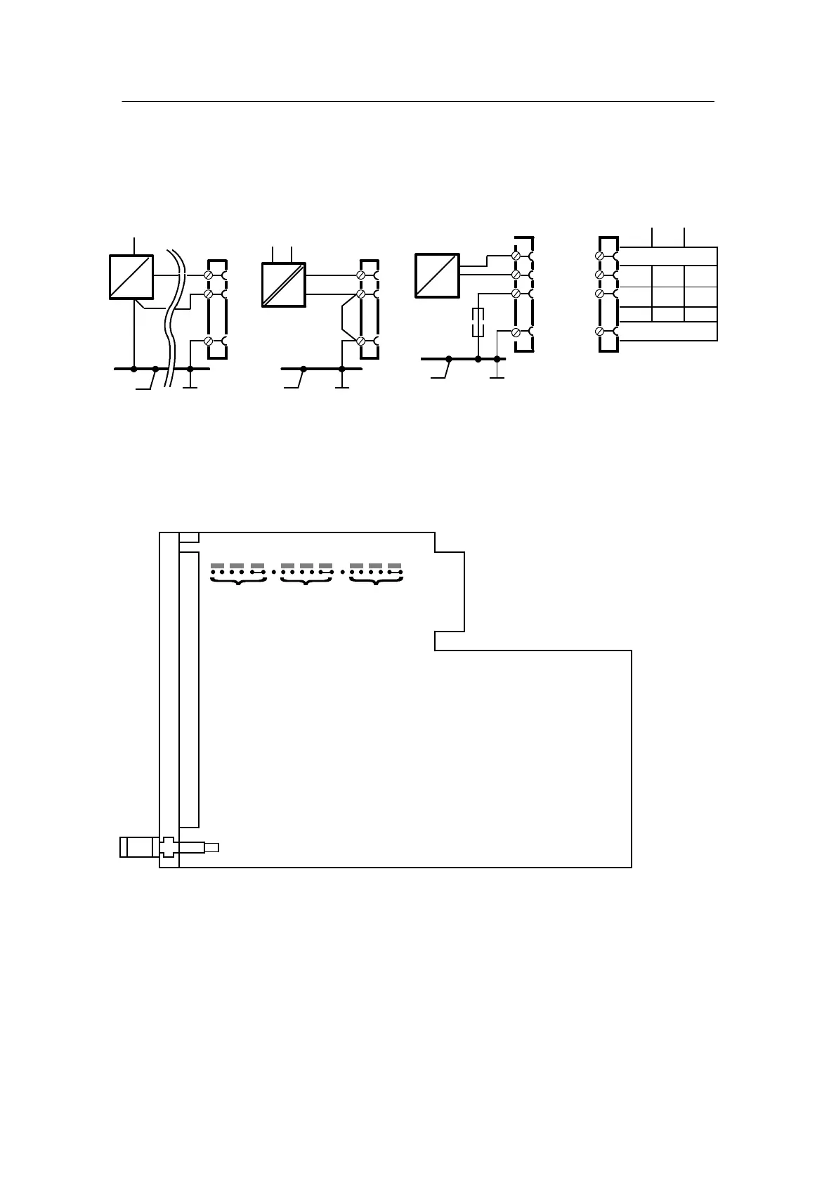
D AE1 to AE3
- Wiring
L+
AE+
AE-
1/1
1/21
1/23
1/20 1/22
1/24
1/19
1/3
AE2AE1
AE3
U I
+
U
H
+U
H
4L 2L
-
≤500 Ω
1)
L+
+
+
I
U
See chapter 2.2.4, page 123 for alternative wiring
SetAE1toAE3to0or4mAinhdEF
AE+
AE-
GND
AE+
AE-
GND
I
-
-
AE+
AE-
GND
GND
1)
potential load impedance from additional instruments
Figure 2-6 AE1 to AE3 U or I wiring diagram
- Jumper settings
AE3 AE2 AE1
1V 10V
Factory setting I (0 to 20 mA)
Main circuit board
C73451-A3001-L32
1V 10V
II
1V 10V
I
Figure 2-7 Jumper settings AE1 to AE3

 Loading...


