2 Installation
2.2 Electrical Connection
2.2.2 Wiring of the standard Controller
Manual
114
SIP ART DR24 6DR2410
C79000-G7476-C153-03
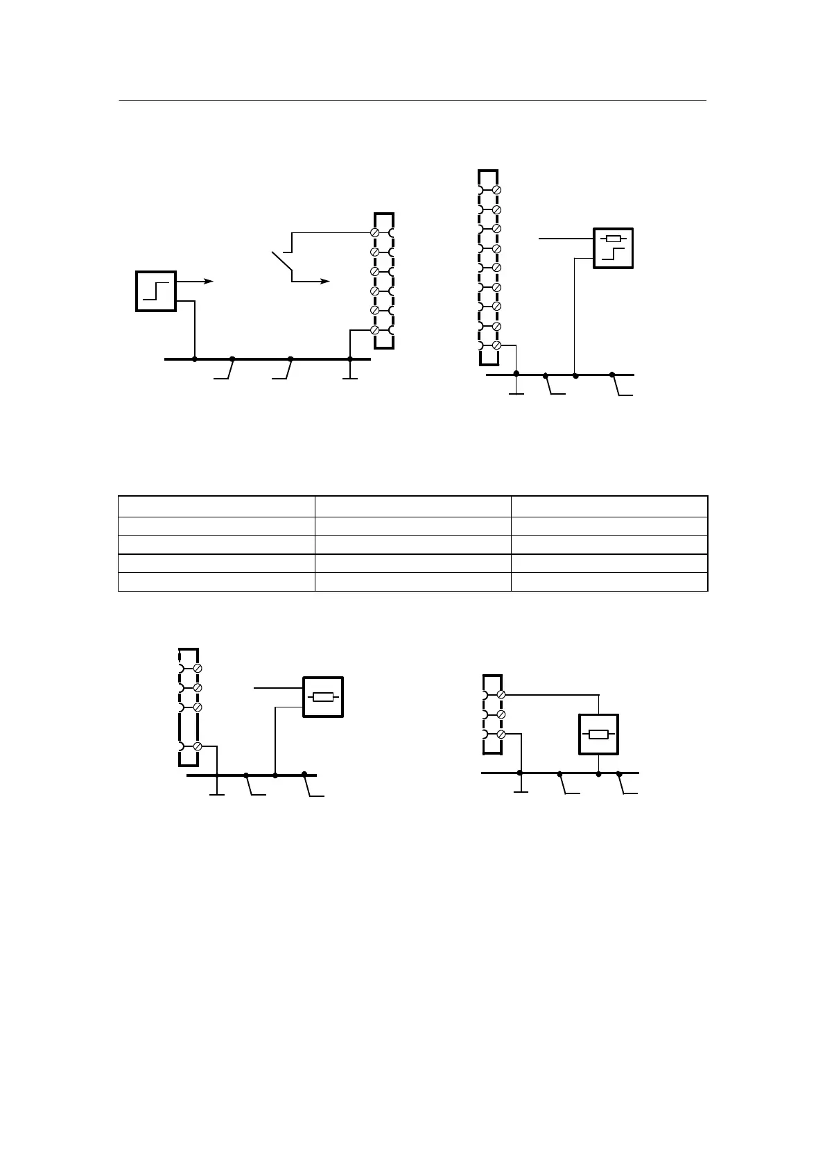
D BE1 to BE4
<4.5 V
>13 V
or
1/3
1/15
1/16
1/17
1/18
1/1
Figure 2-8 BE1 to BE4 wiring diagram
D BA1 to BA8
Figure 2-9 BA1 to BA8 wiring diagram
BAS1
2
3
4
5
6
7
8
1/4
1/5
1/6
1/7
1/8
1/9
1/10
1/11
1/1
≥ 19 V
≤ 50 mA
BE1
BE2
BE3
BE4
L+
GND
If S-controllers CSi* or CSE* are defined in the complex functions, the Δy outputs of the S-con-
trollers are permanently assigned to the digital outputs BA*. See also BAx.1 Assignment via
PUM1 ... 4.
Arithmetic block
+Δy/terminal --Δy/terminal
h01.F BA5 : 1/8 BA6 : 1/9
h02.F BA7 : 1/10 BA8 : 1/11
h03.F BA3 : 1/6 BA4 : 1/7
h04.F BA1 : 1/4 BA2 : 1/5
D AA1 to AA3
≤ 900 Ω
Figure 2-10 AA1 to AA3 wiring diagram
0/4to20mA
1/12
1/13
1/14
SetAA1toAA3to0or4mAinhdEF
1/1
AA1
AA2
AA3
GND
Figure 2-11 L+ c onnection
≥ 20 V
≤ 100 mA
1/3
1/2
1/1
L+
GND
GND
D L+ (auxiliary voltage output)
 Loading...


