2 Installation
2.2 Electrical Connection
2.2.3 Wiring of the Option Modules
Manual
116
SIP ART DR24 6DR2410
C79000-G7476-C153-03
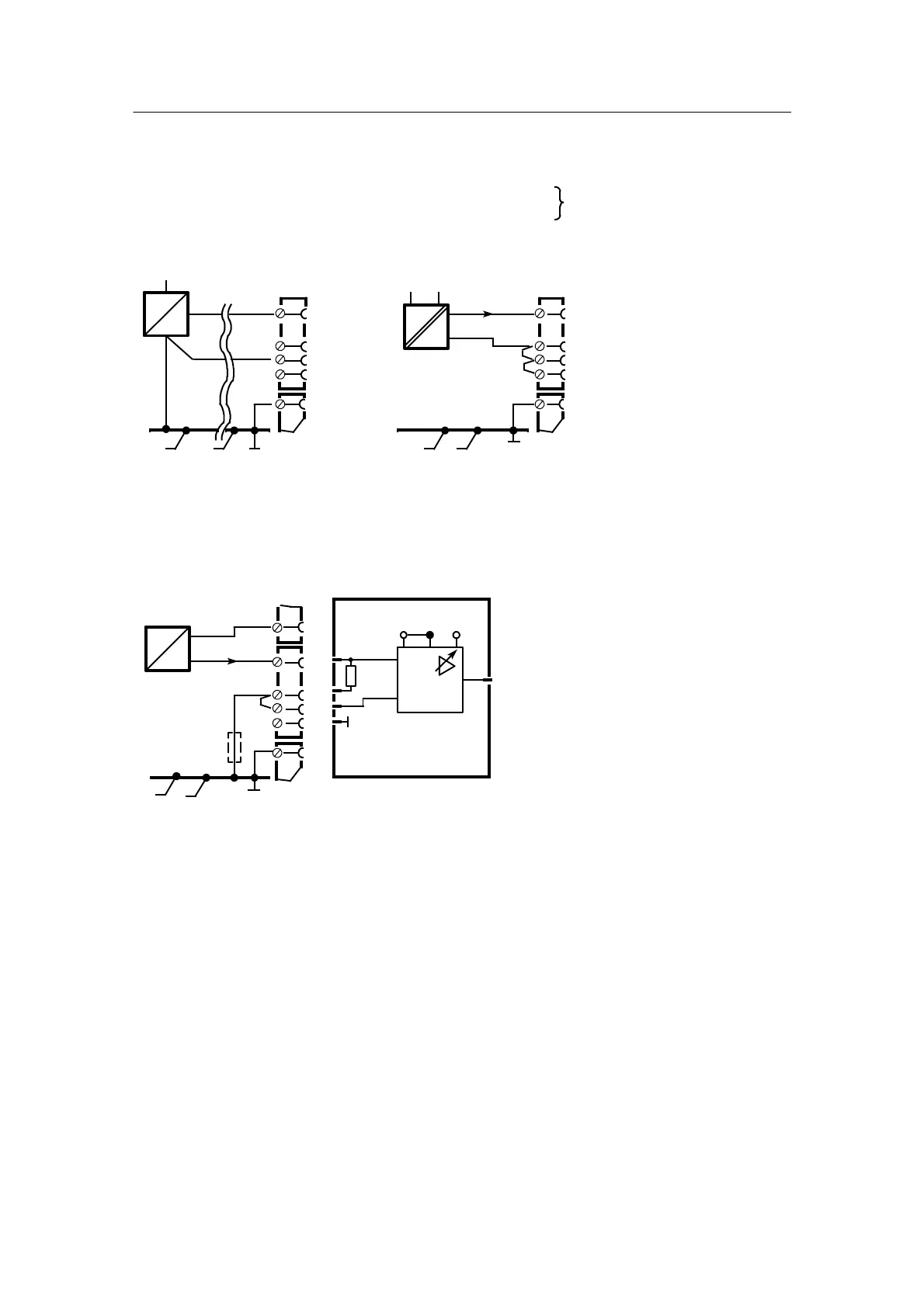
D 6DR2800-8J 1AE, U or Input
AE4 in slot 2, set AE4 to 0 or 4 mA in hdEF
AE5 in slot 3, set AE5 to 0 or 4 mA in hdEF
*
/3
*
/1
+
/2
*
/2
GND
GND
GND
*
=2 or
*
=3
U
H
I 2L
I 4L
*
/4
L+
-
+
1V/10V
x6
GND
x4 x5
1/1
+U
H
U
+
0/2 ... 10 V 0/0.2 ... 1 V
x5=x6/10 V x4=x5/1 V
I
--
0/4 ... 20 mA
x4=x5/1 V
0 ... 500 Ω
1)
I
--
+
49.9 Ω
U
6DR2800-8J
*
/2
*
/4
1/1
*
/4
1/1
*
/3
*
/1
*
/2
1/3
1)
potential load impedance from additional instruments
Factory setting 1 V, x4=x5 (and x7=x8)
Alternative wiring, see chapter 2.2.4, page 123
Figure 2-14 Wiring of U/I module 6DR2800-8J
Measuring ranges:
0to1V/10V/20mAor
0.2V/2V/4mAto
1V/10V/20mA,plus1V/10V
using jumpers on board
 Loading...


