Manual
2 Installation
2.2 Electrical Connection
2.2.3 Wiring of the Option Modules
SIP ART DR24 6DR2410
C79000-G7476-C153-03
117
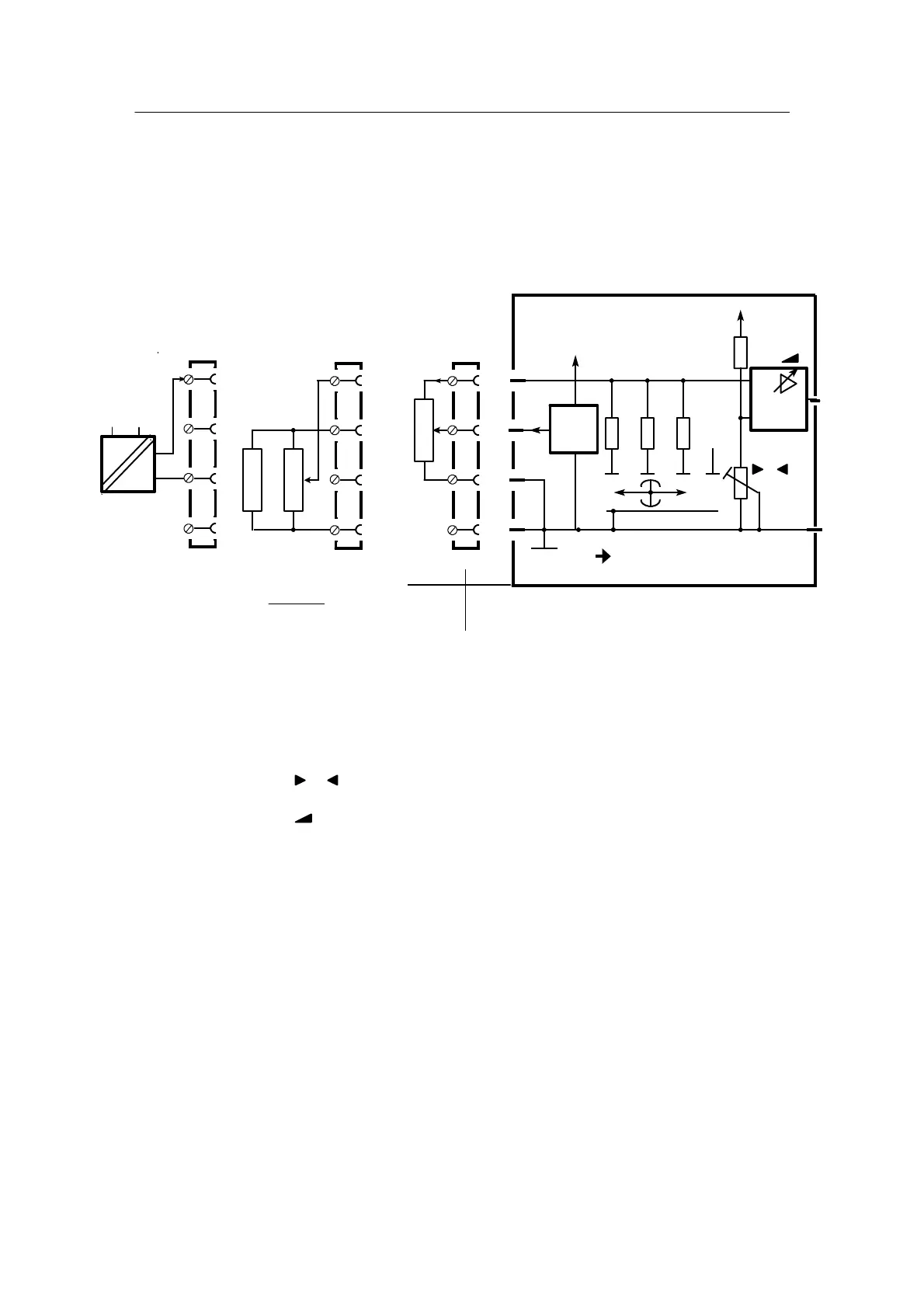
D 6DR2800-8R 1AE, resistance input
AE4 in slot 2; Set AE4 to 0 mA in hdEF
AE5 in slot 3; Set AE5 to 0 mA in hdEF
- Wiring
R
E
ΔR
R
A
R
R
E
ΔR
R
A
S1=200 Ω
RS1
≤ 200 Ω 200 Ω
≤ 500 Ω 500 Ω
≤ 1kΩ 1kΩ
*/2
R
P
*/3
U
REF
*/1
*/2
*/3
*/4
20mA 1kΩ 500Ω 200Ω
49.9 243 332
5mA
Is
+
I
K
R
0
+24 V
S1
*/1
*/4
*/4
U
H
+
I
GND
6DR2800-8R
for potentiometer with
I
s
% 5mAor I
s
=5 mA
R>1kΩ
I R
*=2 or *=3
Factory setting S1 = 200 Ω
S1 = 20 mA
R
P
=
R · 200 Ω
R – 200 Ω
-
-
-
-
-
--
Figure 2-15 Wiring of R module 6DR2800-8R
- Calibration
1. Set sliding switch S1 according to the measuring range
2. Set R
A
using 0 display or analog output (configure accordingly) to
start--of--scale value or 4 mA.
3. Set R
E
using display or analog output to full--scale value or 20 mA.
 Loading...


