2 Installation
2.2 Electrical Connection
2.2.3 Wiring of the Option Modules
Manual
120
SIP ART DR24 6DR2410
C79000-G7476-C153-03
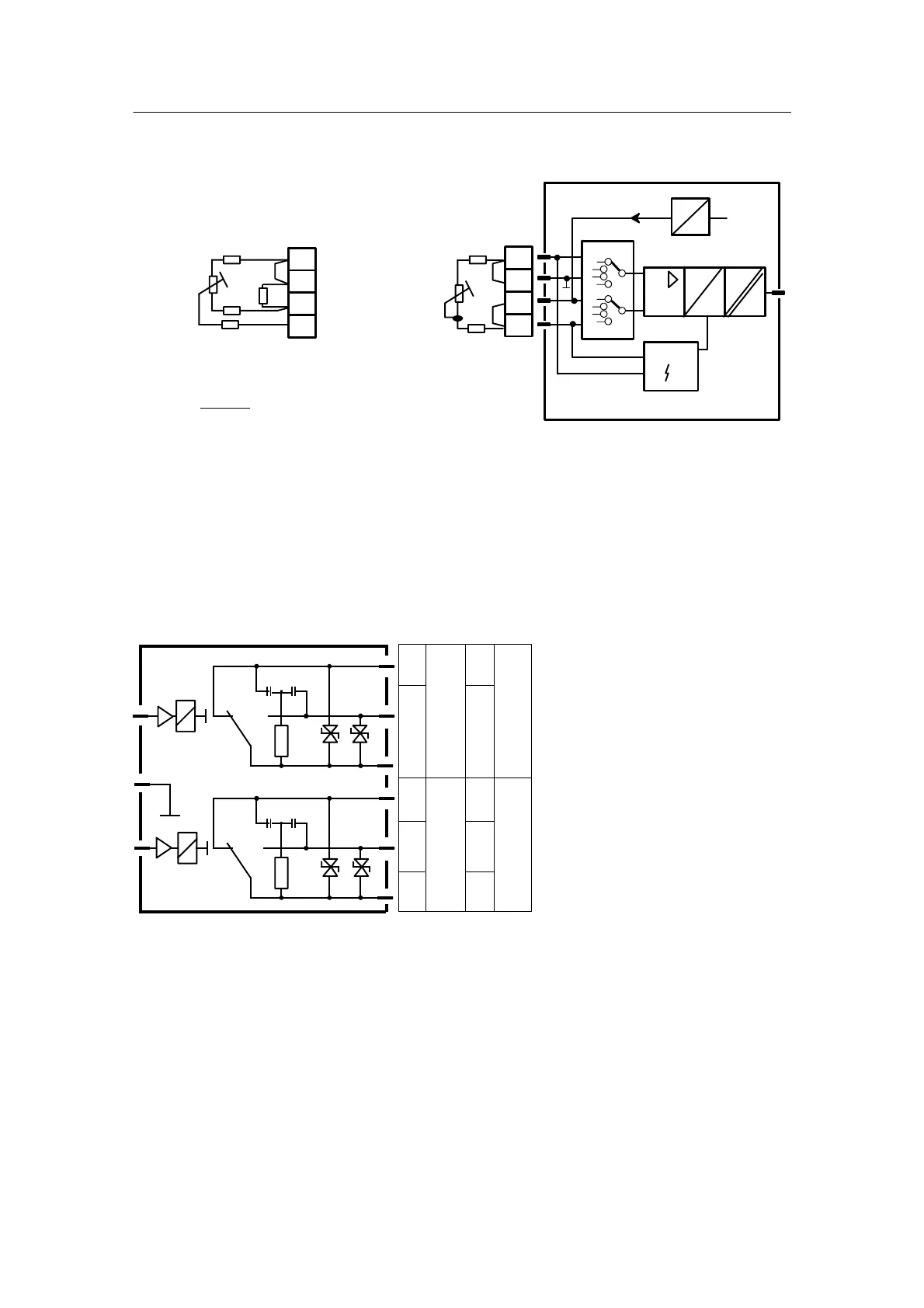
- Pin assignment for resistance transmitter R
2--wire connection3--wire connection
Block diagram of UNI module 6DR2800-8V
R
L4
Rp
R
L1
R
L4
Rp
R
L1
R
L2
1)
R
s
R
L4
≤50 Ω R
L1
+R
L4
≤50 Ω
1)
R
s
jumper impedance only necessary if 2.8 kΩ <R≤ 5kΩ
R
S
⋅R
p
R
S
+R
p
2.8k,Rp>5KΩ not recommended
i
m
U
+REF
+
--
A
D
Sensor
6DR2800-8V
4
3
2
1
4
3
2
1
Figure 2-20 Wiring of UNI module
D 6DR2801-8D 2BA relay 35 V
BA9 and BA10 in slot 5, Set oP5 to 2 rEL in hdEF
BA13andBA14inslot6,SetoP6to2rELinhdEF
Also see BAx assignment on page 114.
6DR2801--8D
22R
1μ
1μ
22R
K1
K2
K2
K1
5/5
5/4
5/6
5/3
5/2
5/1
BA10
BA9
6/5
6/4
6/6
6/3
6/2
6/1
BA14
BA13
AC ≤
≤
≤
35
5
150
V
A
VA
DC ≤
≤
≤
35
5
80
100
V
A
Wat35V
Wat24V
Figure 2-21 Wiring of 2BA (relay) module 6DR2801-8D
 Loading...


