2 Installation
2.2 Electrical Connection
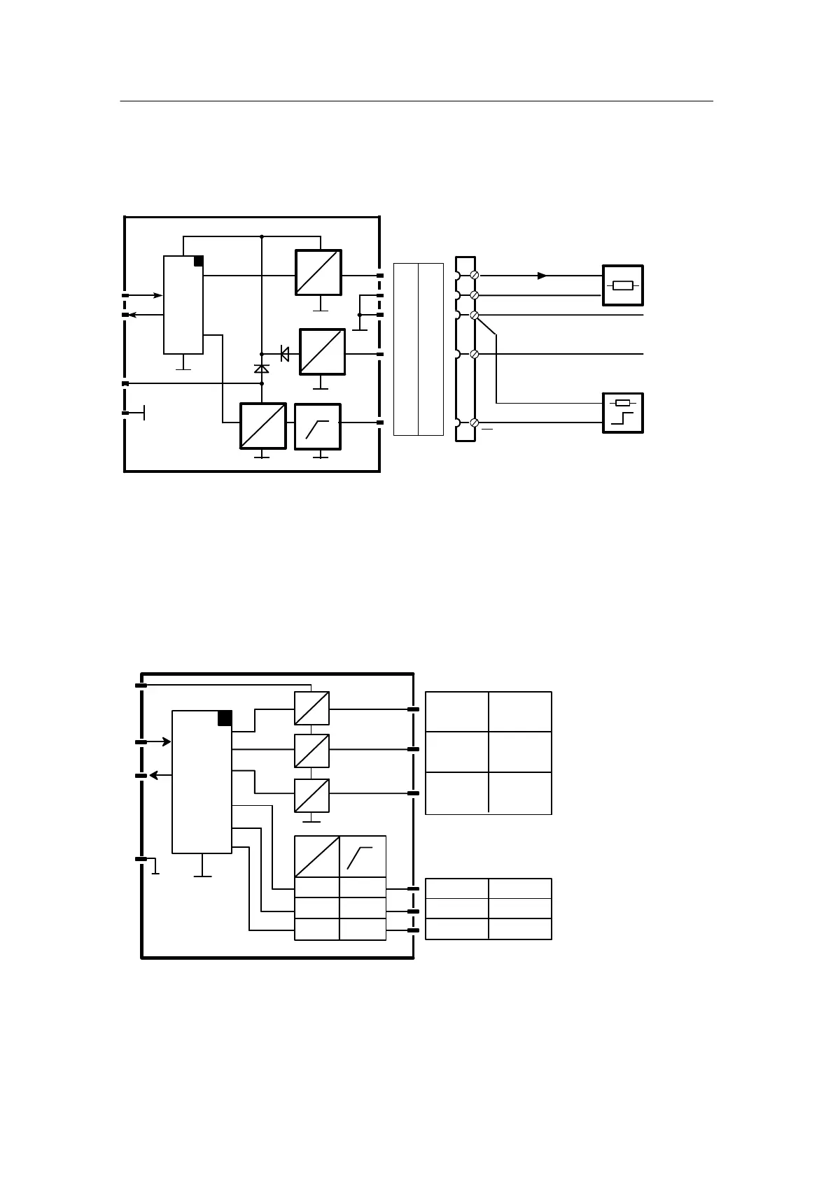
2.2.3 Wiring of the Option Modules
Manual
122
SIP ART DR24 6DR2410
C79000-G7476-C153-03
D 6DR2802-8A (1AA, y
hold
)
AA7 in slot 5 Set oP5 to 1AA in hdEF
AA4 in slot 6 Set oP6 to 1AA in hdEF
I
0/4 ... 20 mA
--
Rxd
L24
Txd
≤ 625 Ω
2)
≥ 19 V
≤ 30 mA
+
U
H
20 ... 30 V, ≤ 70 mA
5V
I
U
=
=
6/5
6/4
6/3
6/2
6/1
AA4 (y)
St
U
H
GND
24 V
5/5
5/4
5/3
5/2
5/1
AA7AA4
1)
UH need only be connected if the output current is to be maintained even in the event of a power failure
in the controller or when removing the module for service work.
2)
Up to 900 Ω possible depending on the supply (see chapter 1.6.3, page 99).
Figure 2-24 Wiring of y
hold
module 6DR2802-8A
D 6DR2802-8B 3AA + 3BE
AA7 to AA9 and BE5 to BE7 in slot 5
AA4 to AA6 and BE10 to BE12 in slot 6
6/5 AA5
5/6 AA9
5/5 AA8
5V
24V
I
Rxd
Txd
U
I
U
I
U
I
6/6 AA6
6/5 AA45/5 AA7
6/2 BE11
5/3 BE7
5/2 BE6
6/3 BE12
6/1 BE105/1 BE5
Figure 2-25 Wiring 3AA/3BE module 6DR2802-8B
 Loading...


