2 Installation
2.2 Electrical Connection
2.2.5 Wiring of the Interface
Manual
130
SIP ART DR24 6DR2410
C79000-G7476-C153-03
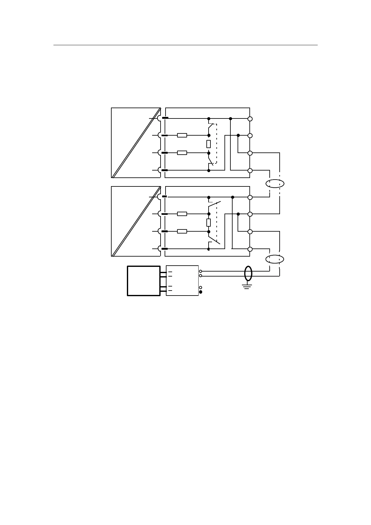
D Wiring the interface PROFIBUS-DP, 6DR2803-8P
Wiring
Canbeinsertedinslot4
B
A
A
RxD/TxD-P
VP
390R
3
6
ON
DGND
5
220R
390R
PROFIBUS-
module
PROFIBUS plug
Instru-
ment 1
(Slave)
RxD/TxD-N
8
B
Instru-
ment n
(Slave)
to
RxD/TxD-P
VP
390R
3
6
OFF
DGND
5
220R
390R
RxD/TxD-N
8
B
A
A
B
PROFIBUS-
module
RxD/TxD-A
RxD/TxD-B
Master
max. number of controllers, without Repeater: 32
max. number of bus users (Slave + Master): 126
6ES7972-
6ES7972-
Switch
ON
Figure 2-42 Principle diagram SIPART DR24 via PROFIBUS-DP and bus plug to master
Note line termination:
The RS 485 bus must be terminated with a characteristic impedance. To do this, the switch in
the bus connector must be switched ”ON” in the ”first” and ”last” bus users. The switch may not
be ”ON” in any of the other bus users. A detailed description and notes on cable laying and bus
cable laying can be found in the Manual Decentral Peripheral System ET200.
Order number 6ES5 998-3ES12.
 Loading...


