1 Technical Description
1.5 Functional Description
1.5.2 Input Functions
Manual
26
SIP ART DR24 6DR2410
C79000-G7476-C153-03
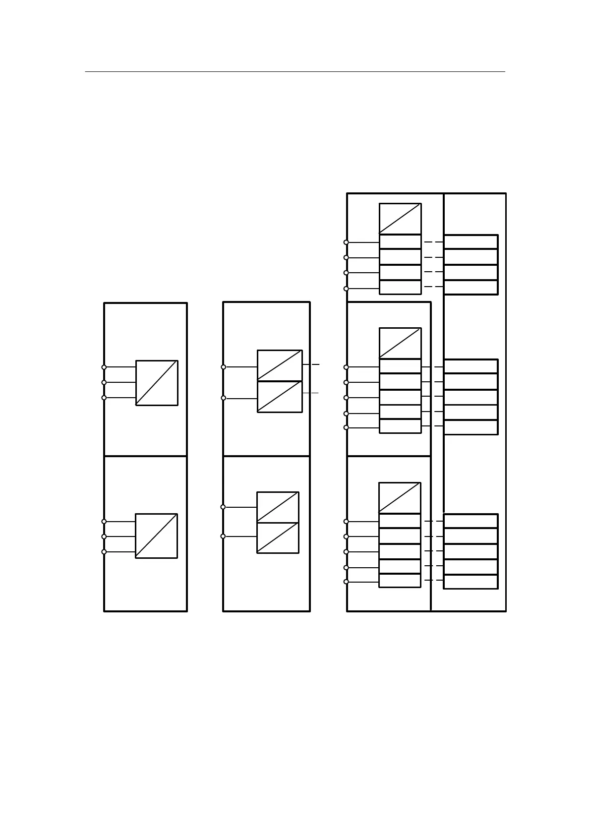
Digital inputs BE1 to BE14
The inputs BE1 to BE4 are located on the basic board. BE5 to 9 and 10 to 14 are connected to
the module 6DR2801--8C at the slots 5 or 6. The digital output modules 6DR2801--8E also con-
tain another two digital inputs in addition to the outputs so that in this case the two digital inputs
BE5/BE6 or BE10/BE11 can be used.
The modules are assigned to the slots in the configuring mode hdEF.
5/1
5/2
5/3
5/4
5/5
6/1
6/2
6/3
6/4
6/5
BE14
BE13
BE12
BE11
BE10
6/3
6/2
6/1
BE12
BE11
BE10
5/1
5/2
5/3
BE5 BE5
1/15
BE1
5V
24 V
BE2
BE3
BE4
1/16
1/17
1/18
bE01 #
bE02 #
bE03 #
bE04 #
BE5
5V
24 V
BE6
BE7
BE8
bE05 #
bE06 #
bE07 #
bE08 #
Slot 5
6DR2801--8C
5BE
BE9
bE09 #
oP5 = 5BE
(hdEF)
5V
24 V
bE10 #
bE11 #
bE12 #
bE13 #
Slot 6
6DR2801--8C
5BE
bE14 #
oP6 = 5bE
(hdEF)
5/1
5V
24 V
BE6
5/6
Slot 5
4BA + 2BE
6DR2801-8E
oP5 = 4BA
(hdEF)
6/1
BE10
5V
24 V
6/6
Slot 6
4BA + 2BE
6DR2801-8E
oP6 = 4bA
(hdEF)
5V
24 V
5V
24 V
5V
24 V
BE6
BE7
Slot 5
3AA + 3BE
6DR2802--8B
oP5 = 3AA
(hdEF)
5V
24 V
Slot 6
3AA + 3BE
6DR2802--8B
oP6 = 3AA
(hdEF)
BE11
Figure 1--7 Input function digital inputs
 Loading...


