1 Technical Description
1.5 Functional Description
1.5.3 Output Functions
Manual
32
SIP ART DR24 6DR2410
C79000-G7476-C153-03
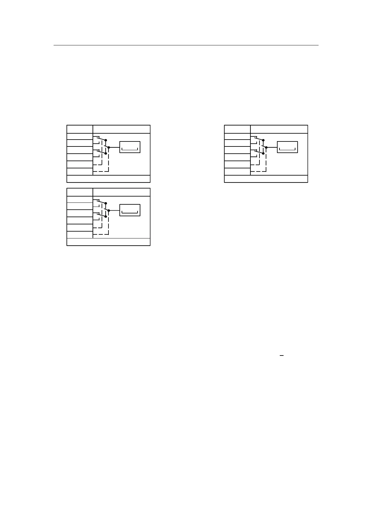
Digital displays dd1 to dd3 (7-segment displays)
The displays serve to display the analog variables (arrangement of displays see figure 1--15,
page 34). The displays can be switched between the data sinks dd*.1 to dd*.4 by the control
inputs dd*.U/dd*.M for quadruple applications.
If the displays are not wired in the configuring mode FCon, the drawn switch positions become
active by defaulting dd*.U/dd*.M with low and the displays go dark by defaulting dd*.1 with
ncon.
∩dd1.1
∩dd1.2
∩dd1.3
∩dd1.4
#dd1.U
#dd1.M
dd1
ncon
ncon
ncon
ncon
Lo
Lo
gn
dr (onPA),dA,dE,dP (oFPA)
∩dd2.1
∩dd2.2
∩dd2.3
∩dd2.4
#dd2.U
#dd2.M
dd2
ncon
ncon
ncon
ncon
Lo
Lo
0000
rd
dr (onPA),dA,dE,dP (oFPA)
∩dd3.1
∩dd3.2
∩dd3.3
∩dd3.4
#dd3.U
#dd3.M
dd3
ncon
ncon
ncon
ncon
Lo
Lo
000
ye
0000
dr (onPA),dA,dE,dP (oFPA)
Figure 1--12 Output function digital displays
The displays have the parameters repetition rate dr (onPA), decimal point dP, start of scale dA
and full scale dE (oFPA). The display comes to rest with dr for restless process variables. The
display is then not activated for every cycle but for every cycle set with dr. The display is acti-
vated independently of dr in every cycle when switching between data sinks.
Start of scale dA and full scale dE specify the numeric range of the calculating value 0 to 1 or 0
to 100 % for the variable to be displayed. (Range --1999 to 19999 for dd1 and dd2, --199 to 999
for dd3). If the start of scale dA is set greater than the full scale dE, this gives a falling display
with a rising input variable.
Exceeding or dropping below the operating range are displayed with oFL or -oFL (o
FL).
Analog displays dA1, dA2 (bar graphs)
The displays serve to display analog variables. You can switch between the data sinks dA*.1 to
dA*.4 with the control inputs dA*.U/dA*.M for quadruple applications.
If the displays dA*.* are not wired in the configuring mode FCon, the drawn switch positions be-
come active by defaulting dA*.U/dA*.M with low and the displays go dark by defaulting da*.1
with ncon.
 Loading...


