Manual
1 Technical Description
1.5 Functional Description
1.5.3 Output Functions
SIP ART DR24 6DR2410
C79000-G7476-C153-03
33
∩dA1.1
∩dA1.2
∩dA1.3
∩dA1.4
#dA1.U
#dA1.M
dA1
ncon
ncon
ncon
ncon
Lo
Lo
rd
dA, dE(oFPA)
∩dA2.1
∩dA2.2
∩dA2.3
∩dA2.4
#dA2.U
#dA2.M
dA2
ncon
ncon
ncon
ncon
Lo
Lo
gn
dA, dE (oFPA) dA-L (hdEF)
Default: dA-L = dA2
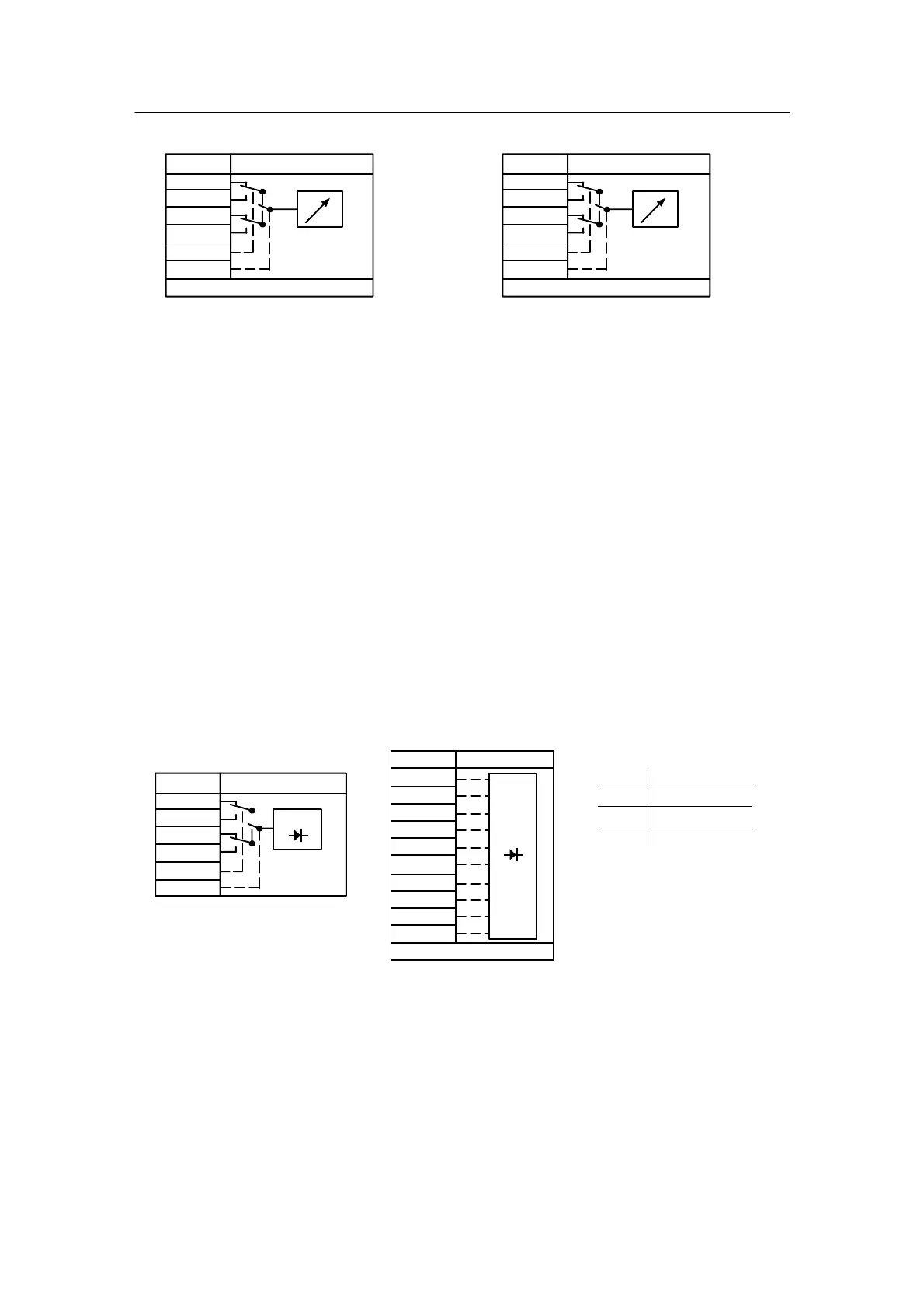
Figure 1--13 Output function analog displays
The display dA2 can also be used optionally as a LED array for analog display or status mes-
sages of 10 digital signals (L14.0 to L14.9). To do this dA--L is defined with 14 in the configuring
mode hdEF. The displays dA1, dA2 have the parameters start of scale dA and full scale dE
(oFPA).
The start of scale and full scale specify the numeric range of the calculating value 0 to 1 or 0 to
100 % for the displaying variable. (Range --199.9 to 199.9). If the start of scale dA is set greater
than the full scale dE, this gives a falling display with a rising input variable. Start of scale 0
means that the 1st lower bar lights, at 100 % the last top bar. The other bars are evenly distrib-
uted over 100 %. Exceeding or dropping below the operating range is displayed by flashing 1st
or last LED.
LEDs L1 to L13, L14
The LEDs signal digital switching states. LEDs L1 to L13 can be switched to other sources for
quadruple applications with the control input L*.U/L*.M.
The drawn switch position becomes active due to defaulting with low; if the LEDs in FCon are
not switched, they are dark. The LEDs L14.0 to L14.9 (bargraph bars) can be used as single
diodes as an alternative to display dA2. To do this dA--L = 14 must be set in the configuring
mode ndEF. The inputs are available for switching to FCon as a result.
#L01.1
#L01.2
#L01.3
#L01.4
#L01.U
#L01.M
L01
Lo
Lo
Lo
Lo
Lo
Lo
gn
↗↗
Example: L1
#L14.0
#L14.1
#L14.2
#L14.3
#L14.4
#L14.5
#L14.6
#L14.7
#L14.8
#L14.9
L14
Lo
Lo
Lo
Lo
Lo
Lo
Lo
Lo
Lo
Lo
dA-L = L14 (hdEF)
↗↗
Color
green
yellow
red
LEDs
L1, 2, 10, 11, 14
L3, 8, 9, 12, 13
L4, 5, 6, 7
gn
Figure 1--14 Output function LEDs
 Loading...


