Manual
1 Technical Description
1.5 Functional Description
1.5.8 Complex Functions (Arithmetic blocks c, d, h)
SIP ART DR24 6DR2410
C79000-G7476-C153-03
67
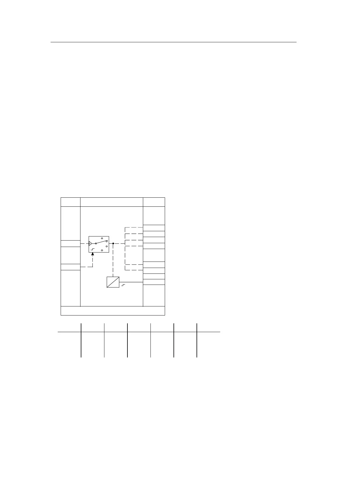
Demultiplexer Cnt1
The demultiplexer can be defined once in FdEF in the arithmetic blocks d0*.F. The counter
reading is output with the demultiplexer binary coded according to the table below . Further
switching takes place edge--controlled at the clock input d*.1 (switching in closed loop, limited
by private parameter StP).
The counter can be driven with a high signal through the reset input d*.2. The position can be
displayed by connecting the output with the display dd3.
This block serves above all for display and key switching in multiple controllers (max. 4)
Example:
- Counter switching Cnt1, e.g. with tA6.1
- Connecting the outputs d*.5/d*.6 with dd*.U/dd*.M (*: 1 to 3) and L10.1/L11.1
By switching over, the appropriate controller signals setpoint w, actual value x, manipulated
variable y are switched over.
The selected controller can be detected at the LED display.
Reset
1
4
ncon
Cnt.1
StP 2, 3, 4
# .1
.1A#
.2A#
.3A#
.4A#
StP
D
A
StP1
2
3
4
.5A#
.6A#
.7A∩
(oFPA)
# .2
Lo
Consecutive number
of the arithmetic block
No. in the cycle
d_.F
n
---
StP 1A 2A 3A 4A 5A 6A
1
2
3
4
1
0
0
0
0
1
0
0
0
0
1
0
0
0
0
1
0
1
0
1
0
0
1
1
Note:
- see example in chapter 7.5, page 191
 Loading...


