1 Technical Description
1.5 Functional Description
1.5.8 Complex Functions (Arithmetic blocks c, d, h)
Manual
74
SIP ART DR24 6DR2410
C79000-G7476-C153-03
- d*.7A to d*.14 (A) digital outputs b1 to b8
Digital outputs b1 to b8 for the digital status signals assigned to the intervals (see CLb1
to CLb8).
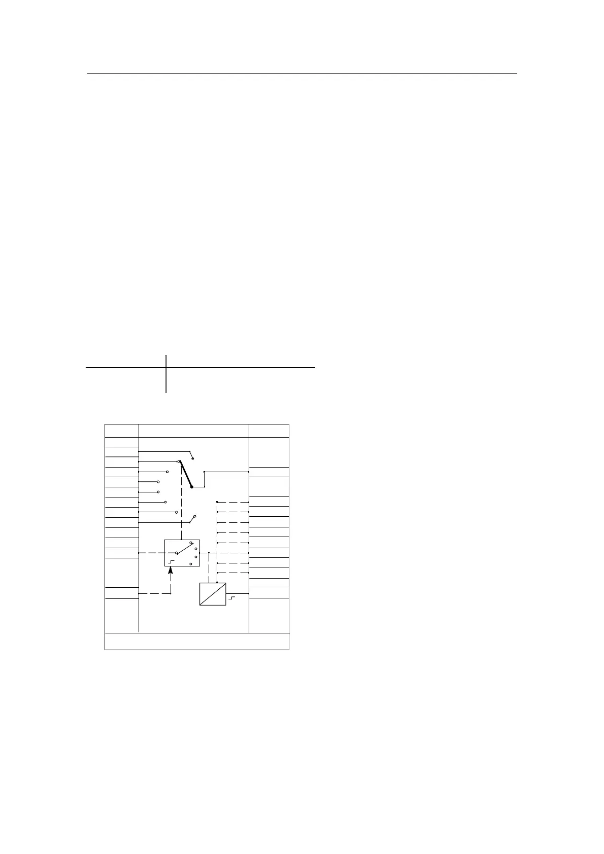
Measuring point switch (multiplexer) MUP1, MUP2
The measuring point switch can be defined twice in FdEF in the arithmetic blocks d0*.F. Up to 8
analog inputs can be connected through to one output (d*.1A) with the measuring point switch.
Further switching takes place edge--controlled at the clock input d0*.9. (switching in closed
loop). Every switching state is displayed by a high signal at a separate output (d*.2A to d*.9A)
These signals can be linked with the preparation inputs of the clock and can select a specific
process program there (for example). In addition the respective position can be displayed by
connecting the output d*.10.(A) with display dd3. (Display format factory setting, display 1 to 8)
The maximum number of measuring points is selected with the private parameter StP (number
of switching steps) (adjustable from 2 to 8); factory setting is 8. The multiplexer can be driven to
position 1 by the reset input (d*.10) with a high signal.
Restart conditions:
Power On Outputs
bAtt = no Switch position 1
bAtt = YES Switch position retained
StP1
2
3
4
5
6
7
8
0.000
0.000
0.000
0.0000.000
0.000
0.000
0.000
1
8
Reset
ncon
Lo
ncon
D
A
∩ .01
∩ .02
∩ .03
∩ .04
∩ .05
∩ .06
∩ .07
∩ .08
#.09
#.10
.1A ∩
.2A #
.3A #
.4A #
.5A #
.6A #
.7A #
.8A #
.9A #
.10(A)∩
MUP1, MUP2
StP
(oFPA)
StP
d0_.F
n
---
Consecutive number of
the arithmetic block
No. in the cycle

 Loading...


