CAUTION
Incorrect mounting
A clearance of 3 mm must be maintained between the magnet and the mounting console in order to ensure correct
measurement of the drive position. The values transferred may be incorrect if this clearance is not given.
● Maintain a clearance of 3 mm between the top edge of the magnet
⑥ and the top edge of the mounting console
①.
Description
D
D
s
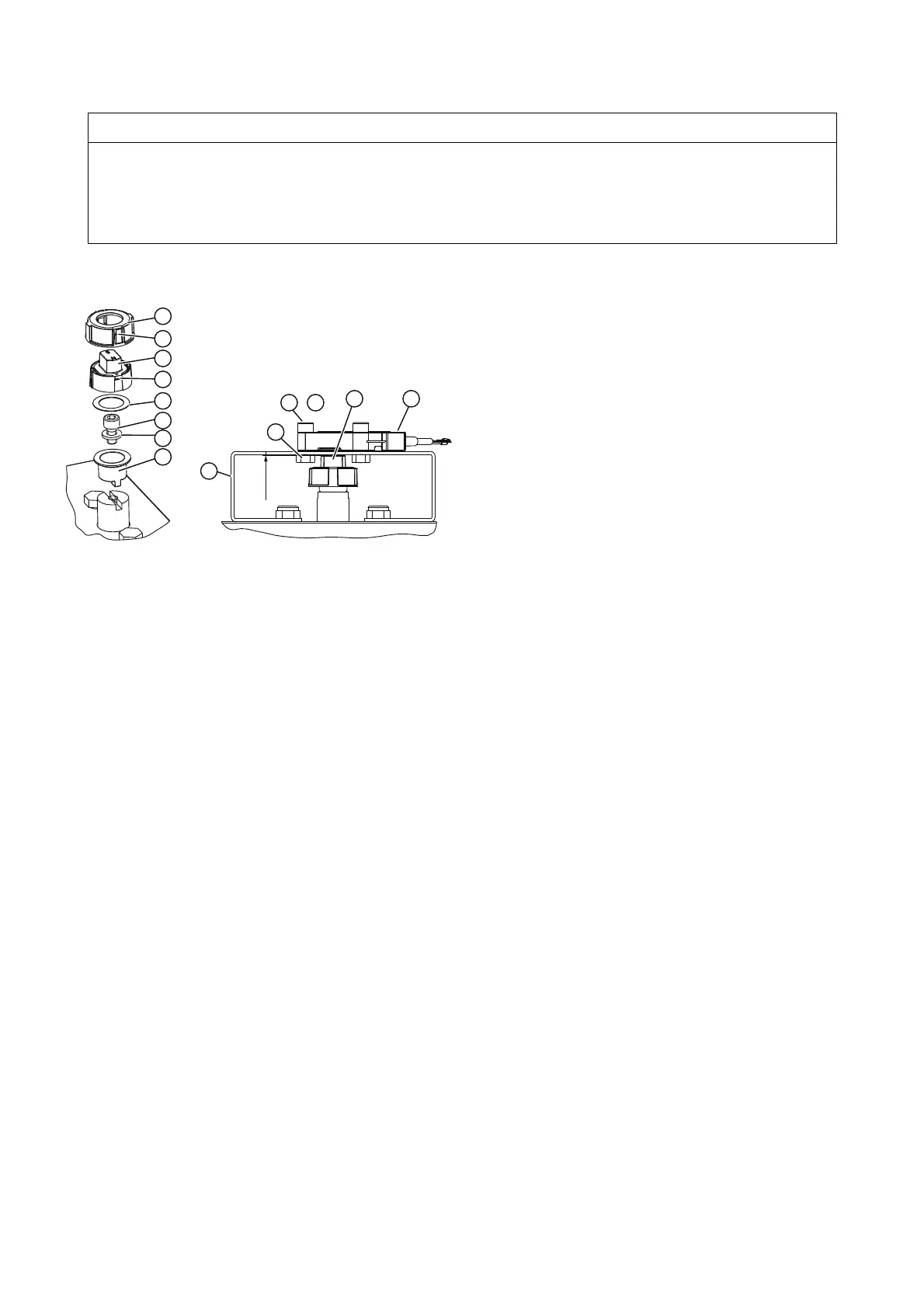
① Mounting console ⑥a Hooks
② Magnet clamp ⑦ Tensioning ring
③ Washer ⑦a Spring element
④ Hex socket head screw size M6x12 ⑧ Hexagon nut
⑤ Plastic washer ⑨ Hex socket head screw size M6x25
⑥ Magnet ⑩ Non-contacting sensor (NCS)
Figure 4-1 Mounting to the rotary actuator
Procedure for the rotary actuator to VDI/VDE 3845
1. Slide the magnet holder
② onto the stub shaft of the rotary actuator.
2. Mount the magnet bracket to the stub shaft using a hex socket head screw
④ and washer ③.
3. Insert the plastic washer
⑤ into the magnet ⑥ and snap the magnet ⑥ onto the magnet holder ②. The magnet can
now be rotated easily on the magnet holder.
4. Slide the clamping ring
⑦ over the magnet ⑥. Make sure that the spring elements ⑦(a) are opposite to the hooks ⑥(a)
on the magnet and that they engage. You will now have more resistance when turning the tensioning ring and magnet.
5. Screw the NCS ⑩ onto the mounting console ① using the hex nut ⑧ and the washer ③. Once the NCS is mounted,
the clearance of 3 mm between the top edge of the magnet
⑥ and the top edge of the mounting console ① is set
automatically.
Procedure for rotary actuators with manufacturer-specific interface
1. Steps 1 to 4 as above.
2. Set a clearance of 3 mm between the top edge of the magnet ⑥ and the top edge of the mounting console ①. Extend
the stub shaft accordingly, or insert washers underneath the NCS housing.
Reference
For information on the scope of delivery, refer to chapter "Scope of delivery of NCS for linear actuators (Page 32)".
SIPART PS2 Non-Contacting Sensor (NCS)
24 A5E00097485-07, 01/2012
 Loading...


