[dwocpka4-080213-01.tif, 2, en_US]
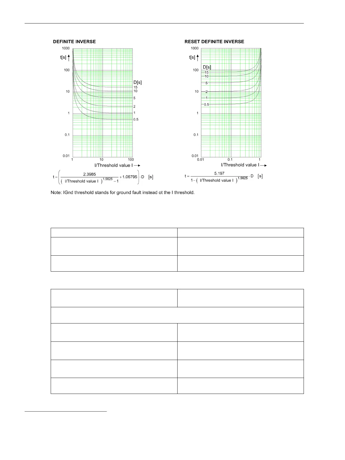
Figure 12-12
Operate Curves and Dropout Characteristic Curves According to ANSI/IEEE
Frequency Operating Range
0.9 ≤ f/f
rated
≤ 1.1 According to specified tolerances
10 Hz ≤ f < 0.9 f
rated
1.1 f
rated
< f ≤ 80 Hz
Slightly expanded tolerances
f < 10 Hz
f > 80 Hz
Active
Tolerances
3I0 measured via I4
56
, method of measurement =
fundamental component
1 % of the setting value or 5 mA (I
rated
= 1 A)
or 25 mA (I
rated
= 5 A), (f
rated
± 10 %)
3I0 measured via I4
57
, method of measurement = RMS value
(33 % harmonics, in relation to fundamental component)
Up to 30th harmonic 1 % of the setting value or 5 mA (I
rated
= 1 A)
or 25 mA (I
rated
= 5 A), (f
rated
± 10 %)
Up to 50th harmonic, f
rated
= 50 Hz 3 % of the setting value or 20 mA (I
rated
= 1 A)
or 100 mA (I
rated
= 5 A), (f
rated
± 10 %)
Up to 50th harmonic, f
rated
= 60 Hz 4 % of the setting value or 20 mA (I
rated
= 1 A)
or 100 mA (I
rated
= 5 A), (f
rated
± 10 %)
Operate time for 2 ≤ I/I threshold value ≤ 20 5 % of the reference (calculated) value
+2 % current tolerance or 30 ms
56
Insignificantly increased tolerances will occur during the calculation of 3I0, maximum factor of 2
57
Insignificantly increased tolerances will occur during the calculation of 3I0, maximum factor of 2
Technical Data
12.10 Overcurrent Protection, Ground
750 SIPROTEC 5, Paralleling Device, Manual
C53000-H5040-C071-1, Edition 05.2018

 Loading...