2.7 Single-Phase Time Overcurrent Protection
203
7UT613/63x Manual
C53000-G1176-C160-2
The voltage across R is then
U
R
= I
1
·(2R
a2
+R
i2
)
Furthermore, it is assumed that the pickup value of the 7UT613/63x corresponds to
half the knee-point voltage of the current transformers. The extreme case is thus
U
R
=U
S
/2
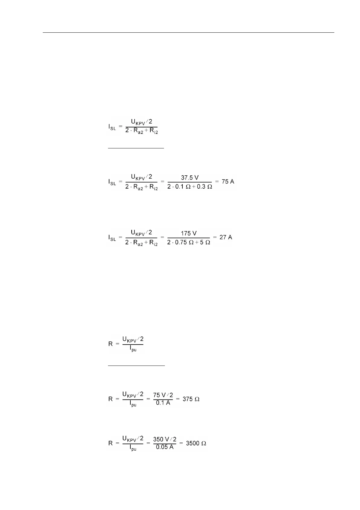
This results in a stability limit I
SL
, i.e. the maximum through-fault current below which
the scheme remains stable:
Calculation example:
For the 5 A CT as above with U
S
= 75 V and R
i
= 0,3 Ω
longest CT connection lead 22 m with 4 mm
2
cross-section; results in R
a
≈ 0,1 Ω
that is 15 × rated current or 12 kA primary.
For the 1-A CT as above with U
S
= 350VandR
i
=5Ω
longest CT connection lead 107 m with 2,5 mm
2
cross-section; results in R
a
≈ 0,75 Ω
that is 27 × rated current or 21.6 kA primary.
Sensitivity Consid-
erations for High-
Impedance
Protection
As before-mentioned, high-impedance protection is to pick up with approximately half
the knee-point voltage of the current transformers. Resistance R can be calculated
from it.
Since the device measures the current flowing through the resistor, resistor and mea-
suring input of the device are to be connected in series. Since, furthermore, the resis-
tance shall be high-ohmic (condition: R >> 2R
a2
+ R
i2
, as above mentioned), the inher-
ent resistance of the measuring input can be neglected. The resistance is then
calculated from the pickup current I
an
and half the knee-point voltage:
Calculation Example:
For the 5-A CT as above
desired pickup value I
an
= 0.1 A (corresponding to 16 A primary)
For the 1-A CT as above
desired pickup valueI
an
= 0.05 A (corresponding to 40 A primary)
 Loading...


