3.1 Mounting and Connections
343
7UT613/63x Manual
C53000-G1176-C160-2
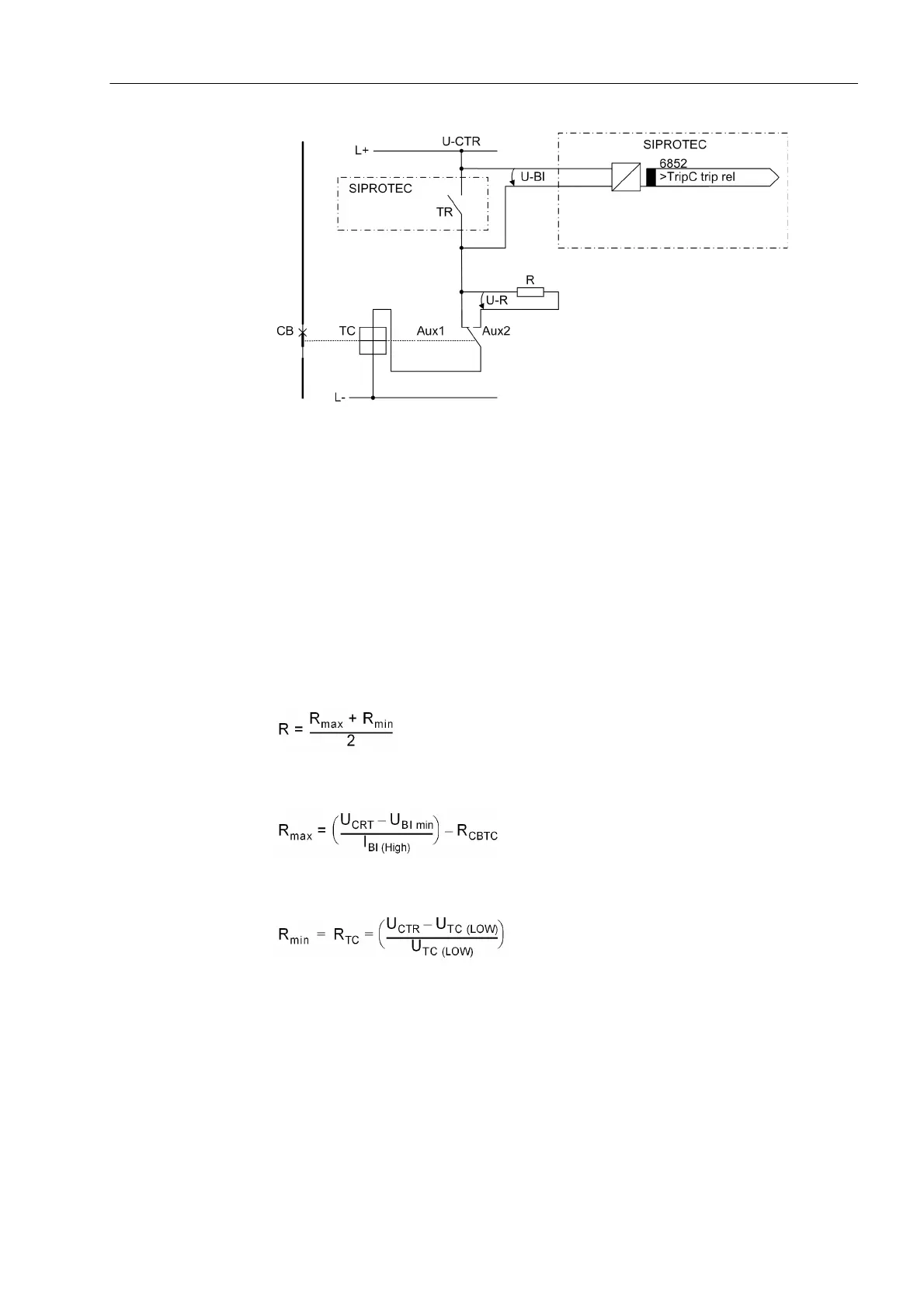
Figure 3-2 Logic diagram of the trip circuit supervision using one binary input
TR Trip relay contact
CB Circuit breaker
TC Circuit breaker trip coil
Aux1 Circuit breaker auxiliary contact (make)
Aux2 Circuit breaker auxiliary contact (break)
U
CTR
Control voltage (trip voltage)
U
BI
Input voltage of binary input
U
R
Voltage across the Bypass resistor
R Bypass resistor
This results in an upper limit for the resistance dimension, R
max
and a lower limit R
min
,
from which the optimal value of the arithmetic mean R should be selected:
In order that the minimum voltage for controlling the binary input is ensured, R
max
is
derived as:
So the circuit breaker trip coil does not remain energized in the above case, R
min
is
derived as:
I
BI (HIGH)
Constant Current with BI on (= 1.7 mA)
U
BI min
Minimum control voltage for BI (= 19 V for delivery setting for nominal
voltage of 24/48/60 V; 73 V for delivery setting for nominal voltage of
110/125/220/250 V)
U
CTR
Control voltage for trip circuit
 Loading...


