2.1 General
59
7UT613/63x Manual
C53000-G1176-C160-2
• M1,M2,M3+M4,M5, i.e. the 5 measuring locations are assigned: M1 to side S1, M2
to side S2, M3 and M4 to side S3, M5 to side S4.
• M1,M2,M3,M4+M5, i.e. the 5 measuring locations are assigned: M1 to side S1, M2
to side S2, M3 to side S3, M4 and M5 to side S4.
Address
229 ASSIGNM. 5M,5S appears if 5 assigned measuring locations (address
212) have been selected for 5 sides (address 213). Only one option is possible:
• M1,M2,M3,M4,M5, i.e. the 5 measuring locations are assigned: M1 to side S1, M2
to side S2, M3 to side S3, M4 to side S4, M5 to side S5.
Assignment of
Sides in Auto-
Transformers
If auto-transformers are protected the additional question arises how the sides of the
protected object are to be handled by the main protection function, the differential pro-
tection. As mentioned above, various possibilities exist how the sides are defined.
Further information is necessary in order to achieve an exact replica of the auto-trans-
former. Therefore, the following addresses only apply to auto-transformers (address
105 PROT. OBJECT = Autotransf. or Autotr. node).
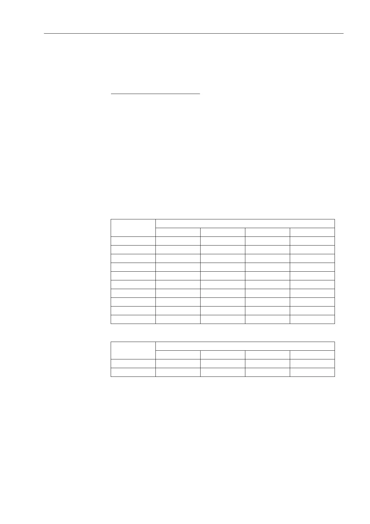
Both of the following tables show which version of configuration is supported for
Autotransf. and for a Autotr. node and which principle of the transformer is ap-
plied. The earth winding is included as a side due to the parameterisation.
Table 2-2 Configuration Versions in an auto transformer
Table 2-3 Configuration Versions in an auto transformer node
address 241 SIDE 1 of the auto-transformer must be assigned to a auto-
connected (primary winding, as recommended above). This is imperative and, there-
fore, cannot be changed.
Address 242 SIDE 2 of the auto-transformer must also be assigned to an auto-
connected (secondary tap as recommended above). This is imperative and, there-
fore, cannot be changed.
For the sides 3 and 4, alternatives exist. If the auto-transformer provides another tap,
the side thereof is declared as auto-connected.
Number
of sides
Configuration types of the side
SIDE 1 SIDE 2 SIDE 3 SIDE 4
2 auto-connected auto-connected — —
3 auto-connected auto-connected auto-connected —
3 auto-connected auto-connected compensation. —
3 auto-connected auto-connected earth.electrode —
4 auto-connected auto-connected auto-connected auto-connected
4 auto-connected auto-connected auto-connected compensation.
4 auto-connected auto-connected auto-connected earth.electrode
4 auto-connected auto-connected compensation. auto-connected
4 auto-connected auto-connected compensation. compensation.
4 auto-connected auto-connected compensation. earth.electrode
Number
of sides
Configuration types of the side
SIDE 1 SIDE 2 SIDE 3 SIDE 4
3 auto-connected auto-connected earth.electrode —
4 auto-connected auto-connected auto-connected earth.electrode
 Loading...


