2 Functions
78
7UT613/63x Manual
C53000-G1176-C160-2
Table 2-4 Terminal designation with surface mounted housing
Voltage Transform-
er Data
If the device is equipped with measuring voltage inputs and these inputs are assigned,
the voltage transformer data are of relevance.
For the 3-phase voltage input, you set at address 801 UN-PRI VT SET the primary
rated VT voltage (phase-to-phase), and at address 802 UN-SEC VT SET the second-
ary rated VT voltage.
If the reverse power protection with high-precision active power measurement is used,
a correction of the angle faults of the current and voltage transformers is particularly
important, as in this case a very low active power is computed from a very high appar-
ent power (for small cos ϕ). In other cases, absolute compliance with the angle of mea-
sured values is usually not required. In 7UT613/63x angle errors are corrected in the
voltage paths. The question of which current transformer set refers to the correction,
is thus irrelevant, and an influence on the currents for differential protection and all
current functions by this correction is avoided. All power functions are corrected on the
other side. The angle correction is not important to the pure voltage functions (overex-
citation protection, undervoltage protection, overvoltage protection, frequency protec-
tion), as the precise phase angle of the voltages is not relevant there. Set the resulting
angle difference of the current and voltage transformers relevant for the reverse power
protection under address 803 CORRECT. U Ang. In electrical machines, determina-
tion of the corrective value is possible at primary commissioning of the machine.
For the 1-phase voltage input, you set at address 811 UN-PRI VT U4 the primary
rated voltage of the connected 1-phase voltage transformer, and at address 812 UN-
SEC VT U4 the secondary voltage. The addresses 811 and 812 must be set if the U4
transformer set has a different reference than the VT SET.
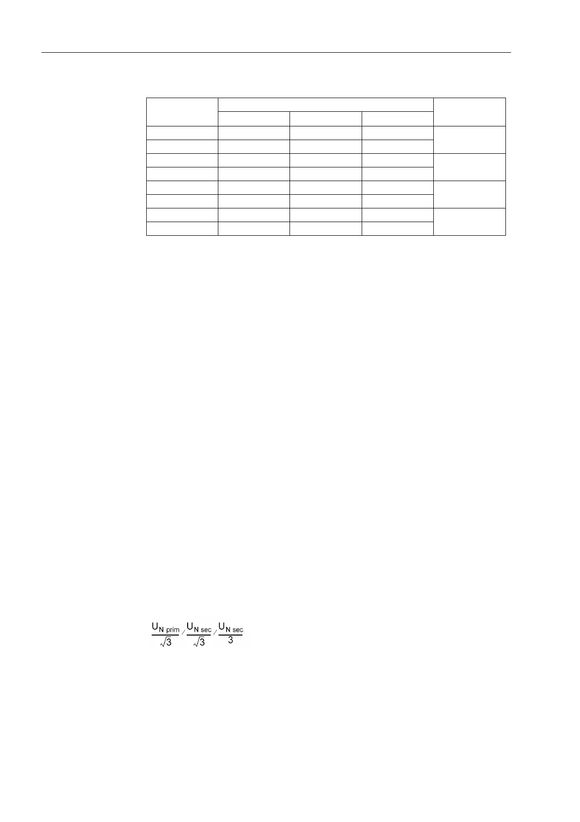
If the single-phase voltage input of a U4 transformer is a Uen transformer and equally
assigned like the main transformer set, then a different transformation ratio of the
single-phase voltage transformer from the three-phase voltage transformer set can be
set under address 816 Uph / Udelta. If the single-phase voltage input at the open
delta winding e-n of the voltage transformer set is connected, the voltage transforma-
tion of the transformer is normally as follows:
Factor Uph/Uen (secondary voltage) 3/sqrt(3) = √3 ≈ 1.73 must be used. For other
transformation ratios, e.g. if the residual voltage is formed by an interposed transform-
er set, the factor must be adapted accordingly. This factor is of importance for the
monitoring of the measured values and the scaling of the measurement and distur-
bance recording signals.
Flush mounted
housing
Corresponds to surface mounted housing, terminal 1-phase current
input
7UT613 7UT633 7UT635
Terminal Q7 22 47 47
IX1
Terminal Q8 47 97 97
Terminal N7 11 36 36
IX2
Terminal N8 36 86 86
Terminal R7 18 43 43
IX3
Terminal R8 43 93 93
Terminal P7 ––32
IX4
Terminal P8 ––82
 Loading...


