SIREMOBIL SPR2-130.812.06 Page 4 of 6 Siemens AG
System Manual Rev. 01 12.02 CS PS 24 Medical Solutions
4 Installation and Startup
• Insert the key switch into the hole from the outside. Make sure that the "0" mark at the
switch is in the vertical position.
• Slide the clamp fitting from the inside on the key switch.
The arrows of the lettering
a1-4 mma point towards the protective plate.
• Tighten the screw (1/Fig. 3) clockwise, until the key switch is fixed firmly in the hole.
• Do not yet install the switch top (4/Fig. 4).
Fig. 3 Fig. 4
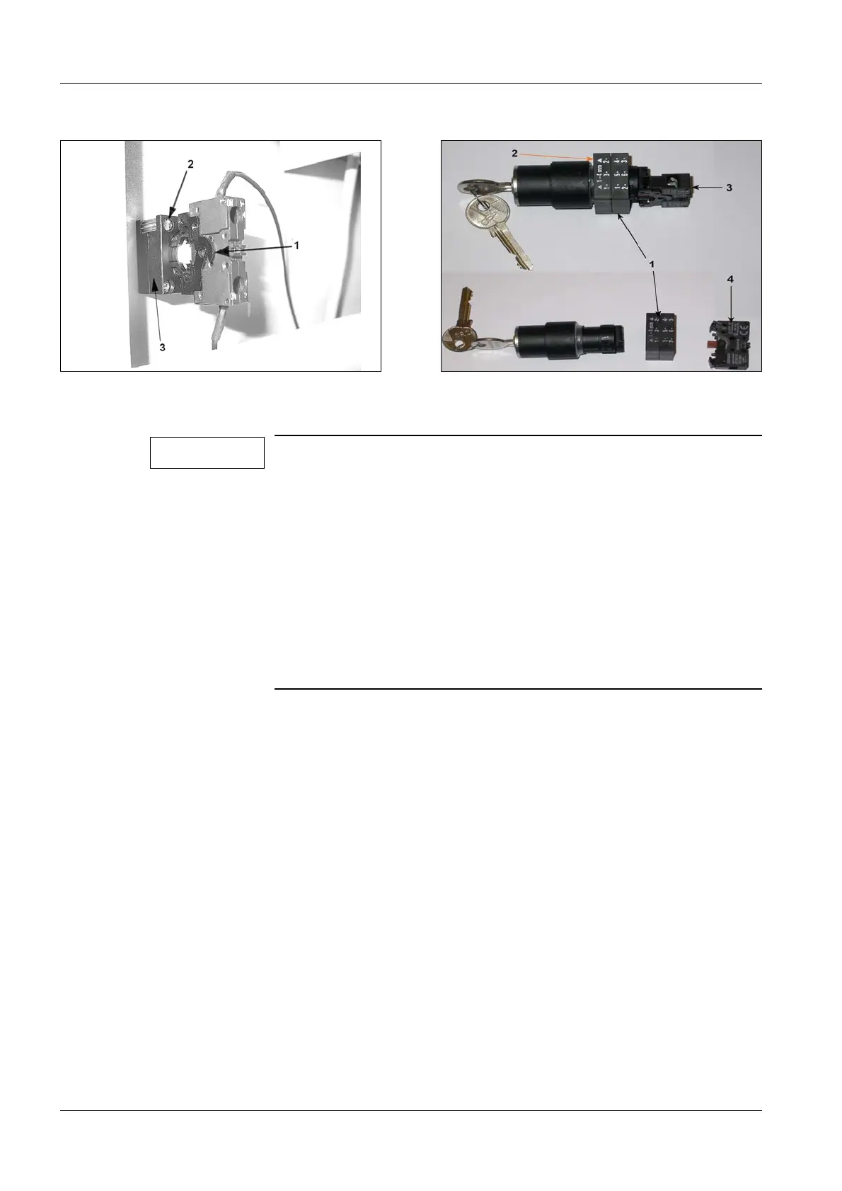
The key switch is delivered ready to assemble (Fig. 4).
For different plate thicknesses, the clamp fitting (1/Fig. 4) can be
pushed onto the key switch at two positions.
Make sure that the clamp fitting is installed with the arrows of the
lettering
a1-4 mma pointing towards the key switch (2/Fig. 4).
Tighten the screw of the clamp fitting (2/Fig. 3) clockwise and
loosen it counterclockwise.
After having pressed the latch (1/Fig. 3) in the direction of the
arrow the switch top (4/Fig. 4) of the key switch can be removed.
The switch top can be placed on the key switch in three different
positions and then locked. In the center position the switch is not
actuated by the cams. Therefore, the switch top must be placed
off-center on the key switch and locked into place (3/Fig. 4).
Note
 Loading...


