Mounting
7.2 Minimum clearances and mounting position
SIRIUS 3RU thermal overload relays / SIRIUS 3RB electronic overload relays
82 Manual, 09/2016, A5E03656507420A/RS-AB/003
Minimum clearances and mounting position
Minimum clearance
A minimum lateral clearance of > 6 mm must be maintained from live and grounded parts.
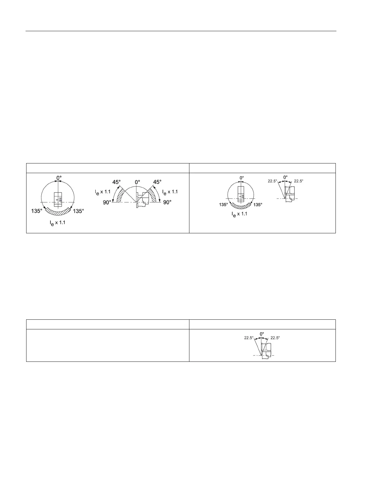
Mounting position for 3RU21 thermal overload relay
The diagrams below illustrate the permissible mounting positions for contactor mounting and
stand-alone assembly for 3RU21 thermal overload relays.
Table 7- 1 Permissible mounting positions for the 3RU21
Overload relay, stand-alone assembly
Contactor + overload relay
The set value is 1.1 times the motor current for a mounting position in the hatched area.
Mounting position of 3RB20 /3RB21 and 3RB30 /3RB31 electronic overload relays
The following diagram shows the permissible mounting position for contactor mounting
for 3RB20 / 3RB21 and 3RB30 / 3RB31 electronic overload relays.
Table 7- 2 Permissible mounting positions of 3RB20 / 3RB21 and 3RB30 / 3RB31
Overload relay, stand-alone assembly
Contactor + overload relay
3RB20 / 3RB21 and 3RB30 / 3RB31 electronic overload relays
can be mounted in any position in stand-alone assembly.

 Loading...


