Interference Spreading
© Siemens AG, 2004. All rights reserved
EMC Installation Guideline – Planning Guide (EMV) – 03.2004 Edition
3-17
3.3 Coupling paths
The coupling path is the transmission path for the noise levels generated by an
interference source. Through them, the noise levels can spread from the
interference source to the interference sink. Different coupling mechanisms exist
for the interference coupling:
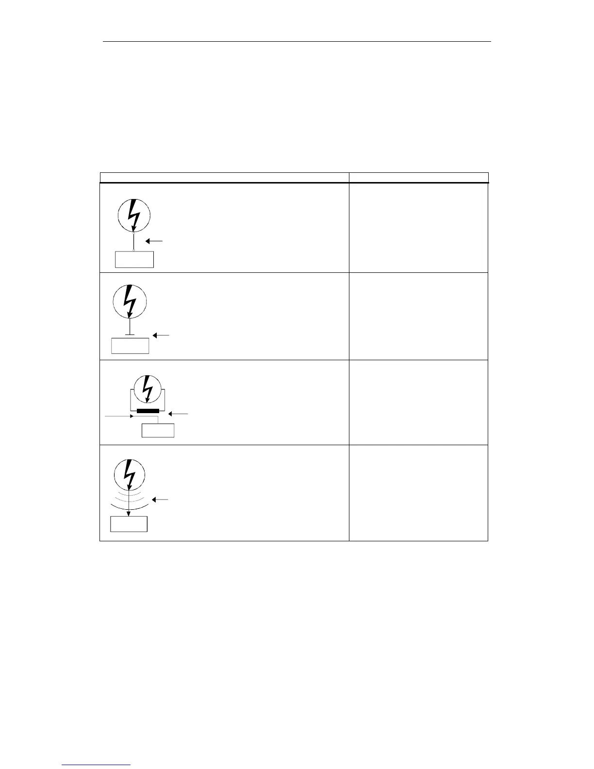
Table 3-3 Coupling mechanisms and their typical interference sources
Coupling mechanism Interference sources
Galvanic coupling
Interference
source
Conductive
coupling path
Interference
sinks
Galvanic or metallic coupling
always occurs when two circuits
jointly use a conductor (e.g.
joint earth line).
• Cycled appliances (mains
influence by converter and
external power supply units)
• Starting motors
• Different potential of component
housings with common power
supply
Capacitive coupling
Interference
source
Capacitive
coupling path
Interference
sink
Capacitive or electrical coupling
occurs between mutually
insulated conductors which are
on a different potential.
• Interference coupling by parallel
running line
• Static discharge of the operator
• Contactors
Inductive coupling
Interference
Inductive
coupling
path
Interference
sink
Useful
signal
source
Inductive or magnetic coupling
occurs between conductor
loops of those at least one is
live. The magnetic flows linked
with the currents induce
interference voltages.
• Transformers, motors, electrical
welding equipment
• Parallel running power line
• Lines with switched currents
• Signal line with high frequency
• Non-switched solenoids
Radiation coupling
Interference
source
Radiated
coupling path
Interference
sink
Radiation coupling is present if
an electromagnetic wave hits a
line formation. The hit of the
electromagnetic wave induces
currents and voltages.
• Adjacent transmitter (e.g. walkie-
talkies)
• Spark paths (spark plugs,
collectors of electric motors,
welding equipment)
 Loading...


