Equipotential Bonding
© Siemens AG, 2004. All rights reserved
4-22 EMC Installation Guideline – Planning Guide (EMV) – 03.2004 Edition
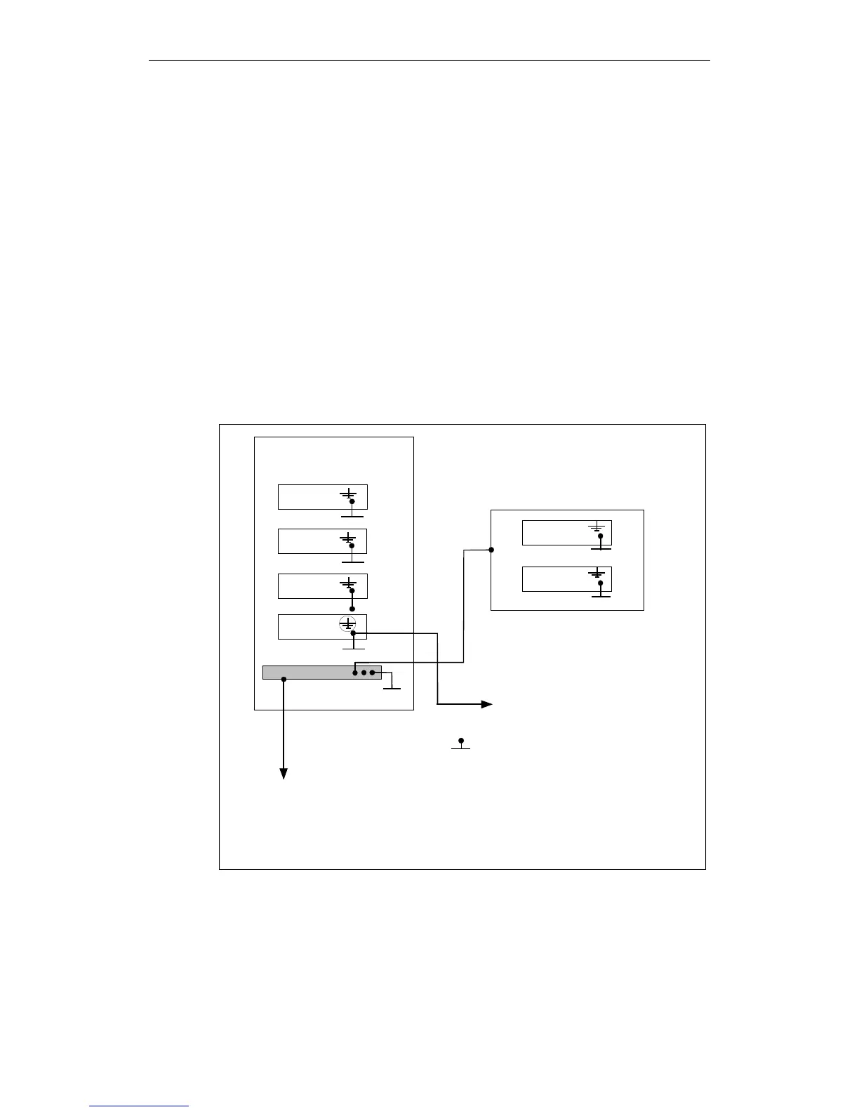
4.2 Equipotential bonding of external components
Control components in different cabinets
If the control cabinets (e.g. control panel, DMP modules) are not housed in the
same cabinet as the associated central device, then the potentials of the cabinets
or the respective central earthing bars must be interconnected:
a) Through a good conducting screw connection of the cabinet housing with each
other or, if this is not possible
b) Through connection of the respective central earthing bars by means of an
equipotential bonding conductor.
Points to bear in mind:
• Cross-section of the equipotential bonding lines ≥ 10mm
2
Cu.
• The distance between the equipotential bonding line and signal connection
lines must be as short as possible (bundle the lines).
Equipotential bonding by meshing via the rear panel of the cabinet
Component 1
XXX
XXX
XXX
XXX
CPU cubicle
Central earthing connector
To motor housing
= Large-area conductive
connection to cabinet housing
Component 4
(SIMODRIVE)
Central earthing bar
Bild A
Component 2
Component 5
XXX
XXX
Component 6
Component 3
1)
1)
=
Short equipment bonding conductor
with insulated component housing mountings
2)
=
PE conductor in motor cable, also used as
equipotential bonding conductor
P
= Equipotential bonding line
2)
Operator panel
XXX
P
Fig. 4-1 Equipotential bonding by meshing
 Loading...


