Equipotential Bonding
© Siemens AG, 2004. All rights reserved
EMC Installation Guideline – Planning Guide (EMV) – 03.2004 Edition
4-23
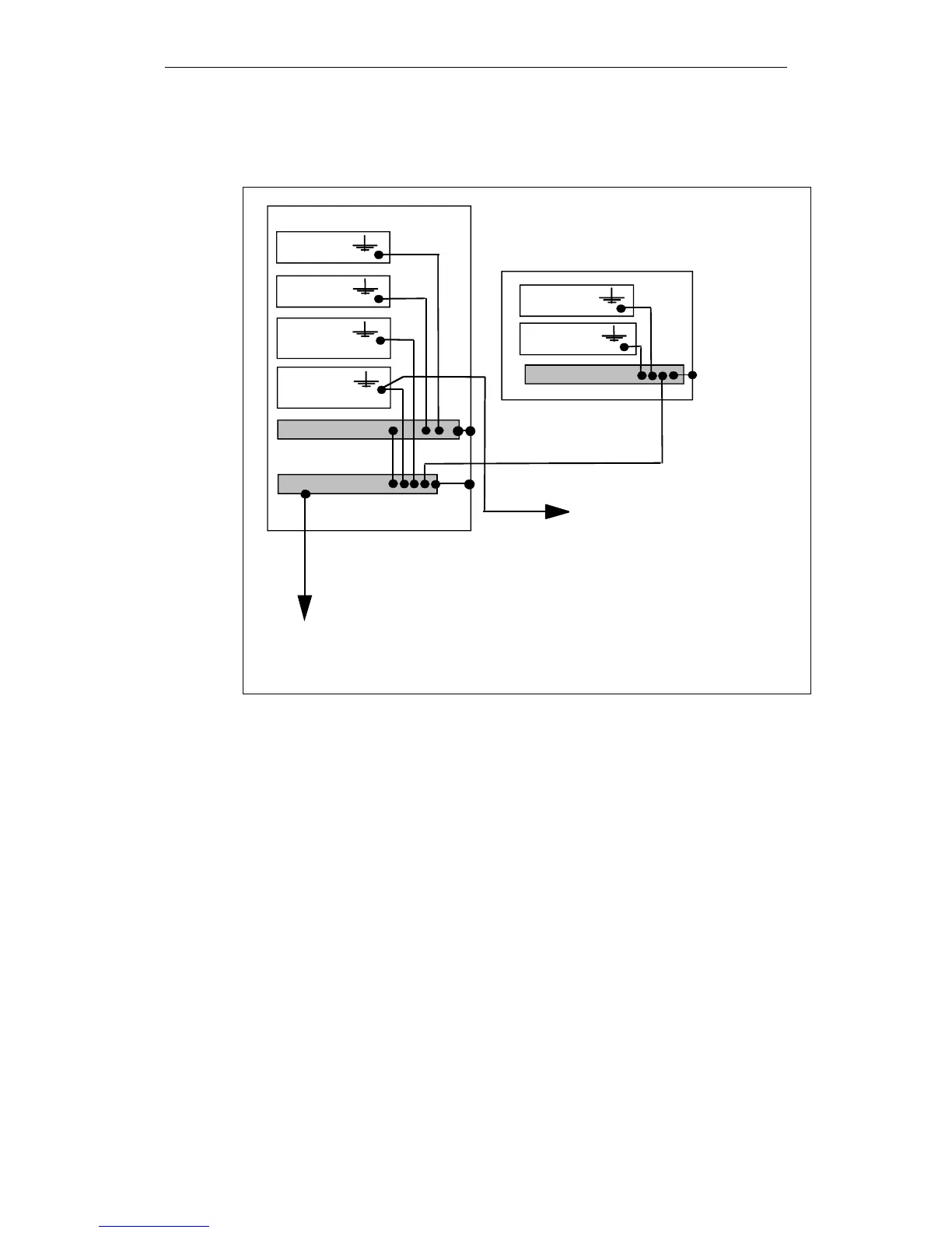
Equipotential bonding by means of equipotential bonding lines
Central earthing bar
Cubicle
Equipotential bond. strip
P
P
P
P = Equipotential bonding conductor
Component 5
Component 6
Operator panel
To motor housing
P
Equipotential bond. strip
P
P
1)
PE = Protective earth
1) = PE in motor cable, also used as
equipotential bonding conductor
1)
Component 1
Component 2
Component 3
(Power component)
Component 4
(SIMODRIVE)
Central earthing connector
Fig. 4-2 Equipotential bonding by means of equipotential bonding lines
Arrangement:
The distance between the signal lines (forward and return conductor) or between
signal lines and the appropriate equipotential bonding lines must be as short as
possible (bundle the lines!). The interference surface between the lines must be
kept as small as possible.
Cross-section:
Cross-section of the equipotential bonding lines ≥ 10mm
2
Cu.
 Loading...


