Equipotential Bonding
© Siemens AG, 2004. All rights reserved
4-24 EMC Installation Guideline – Planning Guide (EMV) – 03.2004 Edition
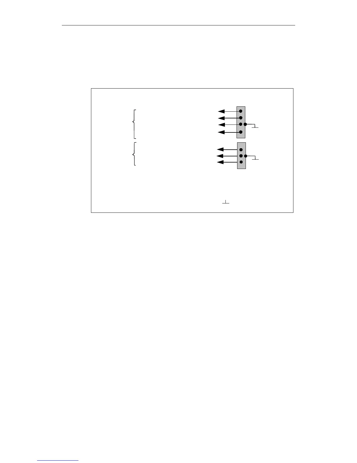
Grouping:
With an insulated component structure or when connecting equipotential bonding
lines of cabinet external components, the equipotential bonding lines must be
arranged separately from the power components and signal-sensitive components.
The equipotential bonding lines must be arranged in groups.
components
Signal-circuit
Power
components
NC
Interface control
PLC
Control electronics
of drive control
0 V cable from ext.
power pack
Relay adapters
Actual-value encoder
Equipotential
bonding strip
XXX
XXX
Earthing bar
= Large-area, conductive connection
to earthed housing
XXX
Fig. 4-3 Arrangement of equipotential bonding lines in groups
 Loading...


