Wiring and Shielding
© Siemens AG, 2004. All rights reserved
6-42 EMC Installation Guideline – Planning Guide (EMV) – 03.2004 Edition
6.2.5 Example of shield connections
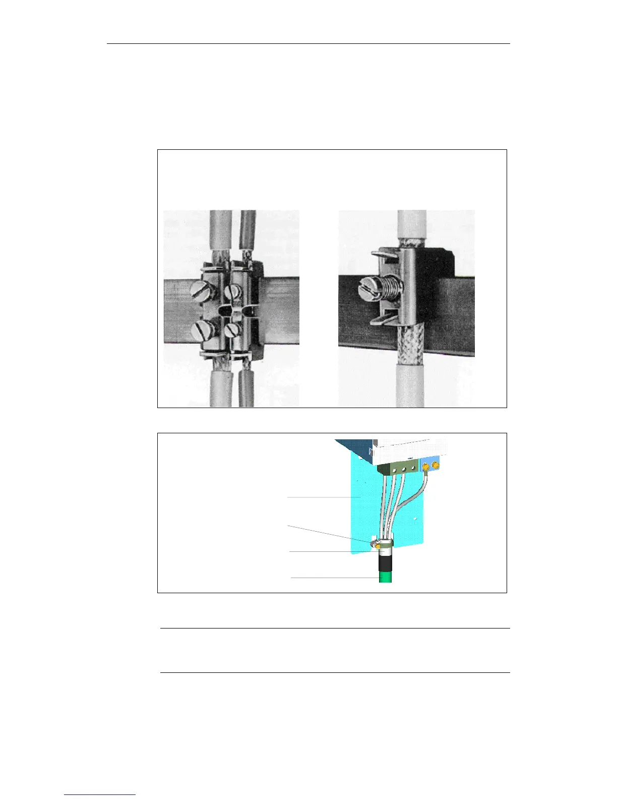
Optimal shield connection
The two following pictures show the shield connection directly to the equipotential
bonding bus.
The figure shows the terminals
of a copper bus. The maximum line
diameter is 15 mm
Order No.: 8US1921-2AC00 (5 mm)
8US1921-2BC00 (10 mm)
The figure shows the rider terminals
of a copper bus. The maximum line
diameter is 10 mm.
Order No.: 8HS7104, 8HS7174, 8HS7164
Fig. 6-6 Shield connection at the equipotential bonding bus
SIMODRIVE
Shielded backshell
Shield bonding clamp
Shield braiding
Motor power
supply cable
Fig. 6-7 Shield contacting by means of shield connection clamp at the shield connection
plate
Caution
Danger of crushing with overtightening of the screws of the terminals (Order No.
8US1921-2AC00 and 8US1921-2BC00).
 Loading...


