Description, device design, dimension drawing
2.4 Status displays and signaling
Selectivity modules
14 Manual, 12.2014, C98130-A7579-A1-1-7629
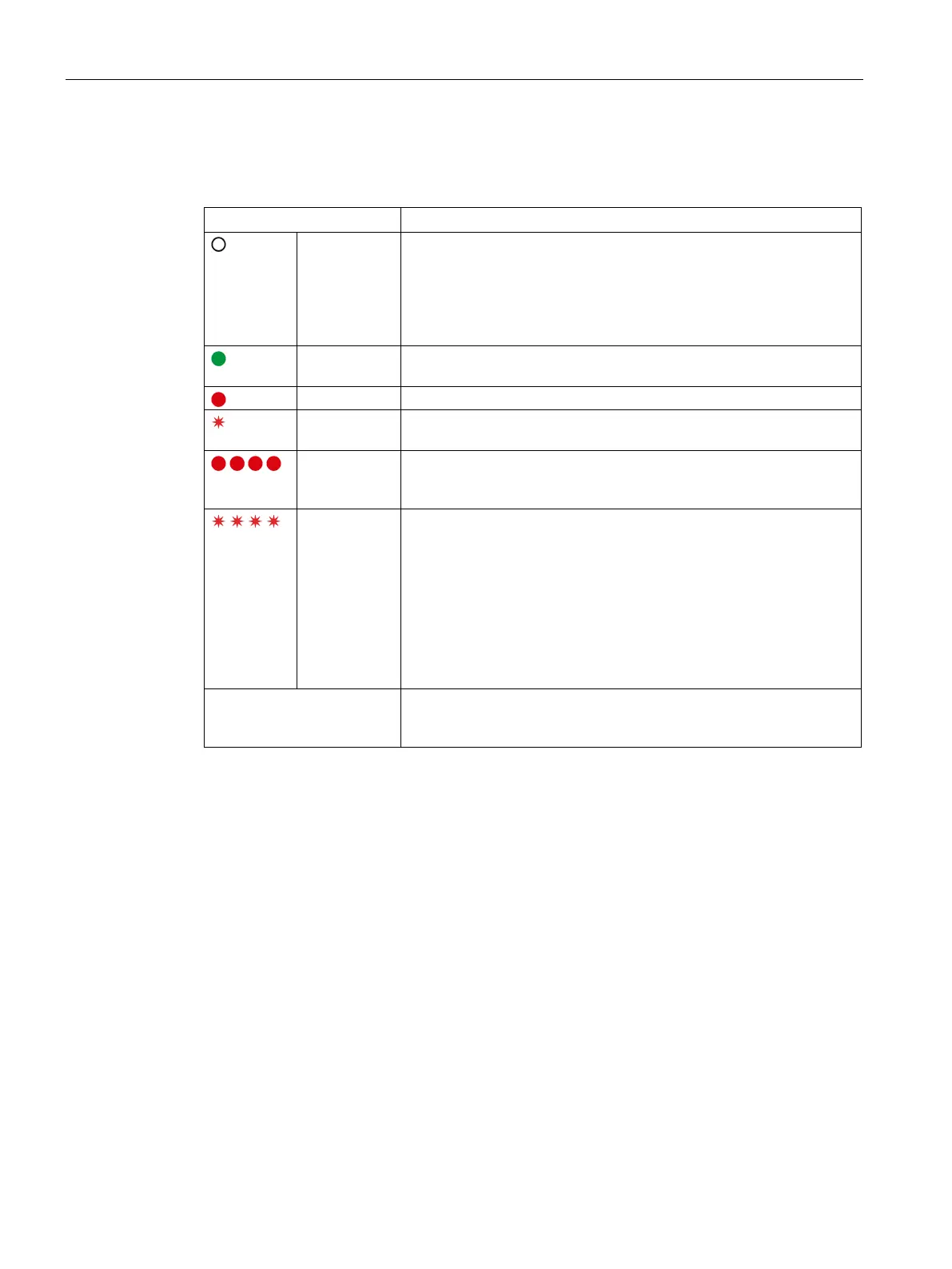
LED ⑧ and group signaling contact ④
Off All LEDs:
• No supply voltage
• Device powering up: After the device has powered up, the outputs
are switched on, taking into consideration the switch-on delay that
has been set.
Lights up
green
Normal operation, output is switched on
Output switched off automatically to due overload
Flashes red Outputs ready to be re
set after an automatic switch off by pressing the
button
Light up red All LEDs are red (after actuating the reset button for a minimum of
8 s):
programming mode for the switch-on delay
Flashes red All LEDs flash red (in the programming mode):
signals the programmed switch-on delay time:
• all LEDs flash 1x simultaneously red, followed by a 2 s pause:
0 ms
• all LEDs flash 2x simultaneously red, followed by a 2 s pause:
24 ms
• all LEDs flash 3x simultaneously red, followed by a 2 s pause:
100 ms
Group signaling contact (NO
contact)
Signal contact 13-14 opens (=quiescent position) when one/several
outputs are switched off as a result of overload or when a fuse rup-

 Loading...


