Description, device design, dimension drawing
2.4 Status displays and signaling
Selectivity modules
Manual, 12.2014, C98130-A7579-A1-1-7629
15
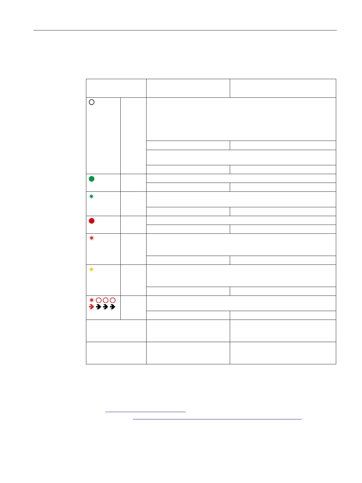
LED ⑧ and group signaling contact or status output ④
6EP1961-2BA11
6EP1961-2BA21
6EP1961-2BA31
6EP1961-2BA41
Off All LEDs:
• No supply voltage
• Device powering up: After the device has powered up, the outputs are
switched on, taking into consideration the switch-on delay that has been
set.
Group signal: Inactive Status output
1*
: -
LED, individual output:
Output defective (internal fuse has ruptured)
Group signal: Inactive Status output
1*
: Ci = '0'
Lights
up green
Normal operation, output is switched on
1*
Flashes
green
Overload at the output: Output current 101…150 % of the response thresh-
1*
Lights
up red
Output switched off automatically to due overload
1*
Flashes
red
Output ready to be reset after an automatic switch off by actuating the but-
ton or remote reset (effective for all outputs that have been automatically
1*
Flashes
orange
Output manually switched off using the button: The state is saved when the
device is swit
ched off, and can only be reset again by pressing the up button
again.
1*
Red
running
light
Device overtemperature: The outputs can be switched-on again once the
temperature is in the normal range.
1*
Group signaling con-
tact (changeover con-
tact)
In the "inactive" state, 11-12 are
connected and 11-14 open
-
Status output - Serial signaling (see Figure 2-5 Status
signaling (Page 16)), ’1’ = 24 V DC /
1*
The status of all four outputs ③ is serially signaled using status output ④ (see Figure 2-5
Status signaling (Page 16)). A frame comprises a start bit START and four status bits Ci
(i=1 … 4), which are each separated by a pause bit P. While the device powers up, or if the
supply voltage is missing, nothing is signaled, the status remains continuously at ’0’. For
SIMATIC-S7 controllers (S7-300/400/1200/1500), a function block for evaluation is available
under (http://www.siemens.com/sitop)
or the direct link (http://support.automation.siemens.com/WW/view/en/61450284).

 Loading...


