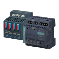
Selectivity modules
Manual, 12.2014, C98130-A7579-A1-1-7629
5
Overview................................................................................................................................................. 3
1 Safety notes ............................................................................................................................................ 7
2 Description, device design, dimension drawing........................................................................................ 9
2.1 Device description ..................................................................................................................... 9
2.2 Connections and terminal designation.................................................................................... 10
2.3 Potentiometer .......................................................................................................................... 12
2.4 Status displays and signaling ................................................................................................. 13
2.5 Buttons and selector switches ................................................................................................ 17
2.5.1 SITOP select ........................................................................................................................... 17
2.5.2 SITOP PSE200U .................................................................................................................... 17
2.6 Electronic overload shutdown and reset ................................................................................. 19
2.6.1 SITOP select ........................................................................................................................... 19
2.6.2 SITOP PSE200U .................................................................................................................... 21
2.7 Setting the switch-on delay time ............................................................................................. 24
2.7.1 SITOP select ........................................................................................................................... 24
2.7.2 SITOP PSE200U .................................................................................................................... 26
2.8 Block diagram ......................................................................................................................... 27
2.9 Dimensions and weight ........................................................................................................... 29
3 Mounting/removal ................................................................................................................................. 31
4 Mounting position, mounting clearances ................................................................................................ 33
4.1 Standard mounting position .................................................................................................... 33
4.2 Other mounting positions ........................................................................................................ 35
4.2.1 6EP1961-2BA00 ..................................................................................................................... 35
4.2.2 6EP1961-2BA11 and 6EP1961-2BA31 .................................................................................. 37
4.2.3 6EP1961-2BA21 and 6EP1961-2BA41 .................................................................................. 39
5 Installation ............................................................................................................................................ 41
5.1 Input side connection .............................................................................................................. 41
5.2 Output-side connection ........................................................................................................... 43
6 Technical data ...................................................................................................................................... 45
6.1 Input ........................................................................................................................................ 45
6.2 Output ..................................................................................................................................... 45
6.3 Efficiency ................................................................................................................................. 48
6.4 Protection and monitoring ....................................................................................................... 48
6.5 MTBF ...................................................................................................................................... 49

 Loading...


