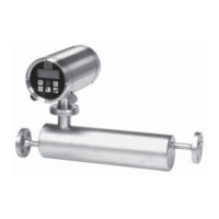
SITRANS F C MASSFLO
16
SFIDK.PS.028.Q1.02
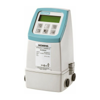
4.2 Signal converter MASS 6000 Ex-d
(continued)
4. Technical data
Enclosure
Material
Stainless steel AISI 316 W1.4435
Rating
Compact mounted on sensor, IP 67 to IEC 529 and DIN 40050
Remote mounted, IP 65 to IEC 529 and DIN 40050
Load
18 - 1000 Hz random, 1.14 G rms, in all directions, to IEC 68-2-36, Curve E
EMC performance Emission EN 50081-1 (Light industry)
Immunity EN 50082-2 (Industry)
Namur Within the value limits according to "Allgemeine Anforderung" with error criteria A in accordance with NE 21
Supply voltage
24 V a.c. 24 V d.c.
Range
20 to 30 V a.c. 18 to 30 V d.c.
Power consumption
6 VA I
N
= 250 mA, I
ST
= 2A (30 msec.) 6 VA I
N
= 250 mA, I
ST
= 2A (30 msec.)
Power supply
The power supply shall be from a safety isolating The power supply shall be from a safety isolating
transformer. Maximal cable core is 1.5 transformer. Maximal cable core is 1.5
Ex approval EEx de [ia/ib] IIC T6, DEMKO 03 ATEX 135253X
Temperature class
T6 T5 T4 T3
Process liquid
temperature
T < 85°C85°C < T < 100°C 100°C < T < 135°C 135°C < T < 180°C
Intrinsic safe terminals in the connections room are in general evaluated as „ia“ for gas group
IIC.
The output terminals 31-32 is set in „active mode“ which means that it can be connected to other
intrinsic safe product, which match the output specification, please look at the specification page
11 and the note 1.
Important
When the terminal 31-32 is in „active mode“ may it only be connected to product there is passive.
The manual must be followed very carefully.
Note 1
Active output shall be evaluated as barrier output, and the L
o
and C
o
is only valid in that case.
When the „active output“ for „current outputs“ and „puls/frequency outputs“ are connected to safe
area, „repeater units“ should be used.
Combination of U and I values for standard barriers in „safe and hazard“ will normally result in to
high values for U and I according to the EN 50020 standard.
„Active outputs“ for „current outputs“ and „pulse/frequency outputs“ is therefore normally used
within safe area to passive or low energy units.
Note 2
HART terminals
This „active output is evaluated to be safe when it is connected to the MTL barrier type MTL 760
with the specifications U
o
: 10 V; I
o
: 200 mA; P
o
: 0.5 W.
This combination gives the maximum external values for the cable: L
C
: 100 µH and C
c
: 20nF.
Note 3
FISCO- (Field Intrinsically Safe Concept) – can depending on the circumstances, be installed so
it complies with EEx ia IIC/IIB or EEx ib IIC/IIB. The instruction manual covering „Profibus“ must
be followed carefully. The output from the terminals is I
o
: 50 mA; U
o
: 1.3 V.
Terminals 81-82 83-84 & 89-90 85-86 & 87-88
U
o
[V] 16 12 12
I
o
[mA] 126 6 4.6
P
o
[W] 0.51 0.018 0.014
L
o
or [mH] 2.2 or 10 10
L
o
/R
o
[µH/Ω] 105
C
o
[nF] 200 200 200
Intrinsically safe sensor
interface
 Loading...