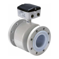
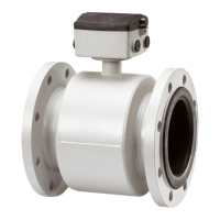
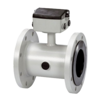
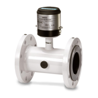
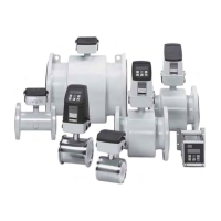
MAG 8000 & MAG 8000 CT
12
SFIDK.PS.026.D9.02
Connection diagram for
115/230 V AC (mains) or
12-24 V AC/DC (line)
power supply
Mains power input: Factory mounted PUR cable with 2 x 1 mm
2
(brown wire, blue wire)
cable length = 3 m
Mains power input: Brown wire - L (line, hot) and blue wire - N (neutral, cold)
Mains power output: Battery connector - female with blue wire and yellow wire, blue wire is
ground. The battery connector - female has to be connected to the
male connector 3.6 V DC on the PCB board
Battery backup input: Battery connector - male with black wire and red wire, black wire is ground.
The battery connector - male has to be connected to the female
connector on the backup battery
Functional ground: Black wire with terminal must be connected to MAG 8000 or MAG 8000 CT
encapsulation with a screw
Mains power supply has to be connected to a switch, near the flowmeter, according to IEC 61010-1
clause 5.4.3.d
115/230 V AC (mains)
power supply
Line power input: Factory mounted PUR cable with 2 x 1 mm
2
(brown wire, blue wire)
cable length = 3 m
Line power input: Brown wire - L (line, hot, positive) and blue wire (neutral, cold, negative)
Line power output: Battery connector - female with blue wire and yellow wire, blue wire is
ground. The battery connector - female has to be connected to the
male connector 3.6 V DC on the PCB board
Battery backup input: Battery connector - male with black wire and red wire, black wire is ground.
The battery connector - male has to be connected to the female
connector on the backup battery
Functional ground: Black wire with terminal must be connected to MAG 8000 or MAG 8000 CT
encapsulation with a screw
12-24 V AC/DC (line)
power supply
3. Electrical connection

 Loading...


