M
Molly BarrettSep 12, 2025
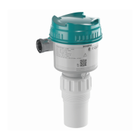
What to do if Siemens Measuring Instruments sensor is nearing its lifetime limit?
- Llauren50Sep 12, 2025
If your Siemens Measuring Instruments sensor is nearing its lifetime limit, replacement is recommended.
What to do if Siemens Measuring Instruments sensor is nearing its lifetime limit?
If your Siemens Measuring Instruments sensor is nearing its lifetime limit, replacement is recommended.
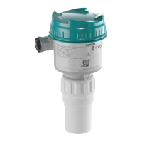
What to do when Siemens Measuring Instruments device is nearing its lifetime limit?
If your Siemens Measuring Instruments device is nearing its lifetime limit, replacement is recommended.
Why is my Siemens Measuring Instruments device overheating?
If the internal temperature of your Siemens Measuring Instruments device exceeds specifications, it's operating outside its temperature range. To fix this, lower the ambient temperature to cool the device. Note that the fault code will persist until a manual reset is performed using PDM or the LCD interface.
What to do if Siemens Measuring Instruments can't get a measurement in time?
If your Siemens Measuring Instruments device fails to get a measurement within the Failsafe timer period, it could be due to faulty installation, material buildup, or the presence of foam. To resolve this, ensure the installation details are correct, check for and remove any material buildup, and adjust process conditions to minimize foaming. If the problem continues, it is recommended to contact your local Siemens representative.
How to modify a parameter via remote communications on Siemens device?
To resolve the issue of not being able to modify a parameter via remote communications on your Siemens device, ensure that remote operation is enabled. Also make sure that Write Locking is Off.
Why does my Siemens Transmitter read empty when the vessel is not empty?
To resolve the issue of your Siemens Transmitter reading empty when the vessel is not empty, it could be reading the vessel bottom through low dK material. Increase the TVT manually at the vessel bottom region, set the Far Range to a lower value, or lower the TVT hover level.
What to do if the reading is frozen on my Siemens sitrans lr 460 Transmitter?
If the reading on your Siemens Transmitter is frozen, this may be due to antenna buildup. You should clean the antenna, install a PTFE dust cover, or use the Air Purge option. It could also be caused by low dK and low bulk density material. In that case, lower the echo confidence threshold.
Why is the reading fluctuating on my Siemens Transmitter?
If the reading on your Siemens Transmitter fluctuates, it is normal due to solids’ sloped surfaces. You can reduce the response rate, decrease fill/empty parameter values, or increase the filter time constant in AIFB.
Why is the PLC value not equal to the displayed value on my Siemens sitrans lr 460?
If the PLC value isn't equal to the displayed value on your Siemens Transmitter, make sure you're looking at the correct spot in the PLC by checking the network to verify that you are communicating.
What to do if the reading on my Siemens sitrans lr 460 is too slow?
If the reading on your Siemens Transmitter is too slow, lagging behind actual level changes, increase the response rate. You can also turn off Window tracking, change the fill/empty rate parameter values, or increase the filter time constant in AIFB.
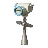
| Device Type | Radar Level Transmitter |
|---|---|
| Communication | HART, PROFIBUS PA, FOUNDATION Fieldbus |
| Enclosure | Aluminum or Stainless steel |
| Accuracy | ± 2 mm |
| Process Temperature | -40 to +200 °C (-40 to +392 °F) |
| Process Pressure | Up to 40 bar |
| Output Signal | 4 ... 20 mA HART, PROFIBUS PA, FOUNDATION Fieldbus |
| Enclosure Rating | IP66 / IP67 |
| Approval | ATEX, IECEx, FM, CSA |
| Beam angle | 4° |
| Ambient temperature | -40 to +80 °C (-40 to +176 °F) |
Explains how to change parameters using handheld programmer or PC.
Details power supply requirements and fuse specifications for the device.
Lists accuracy, deadband, and measurement range specifications.
Guidance on selecting an appropriate location for device installation.
General steps for connecting power and cables to the device.
Specific wiring instructions for HART communication.
Specific wiring instructions for PROFIBUS PA communication.
Specific guidelines for installation in hazardous environments.
Steps to power up the device and its initial operational state.
Resets all parameters to default, excluding device addresses.
Initial steps of the wizard for basic setup.
Setting the upper limit for level measurement.
Setting the unique network address for PROFIBUS or HART.
How to set the PROFIBUS address locally or remotely.
Sets the device's reaction speed to measurement changes.
Setting the low calibration point relative to the sensor reference.
Selects algorithm for extracting the true echo from the profile.
Sets a blind zone in front of the antenna where echoes are ignored.
Enabling or learning the TVT curve for auto false echo suppression.
Defines maximum rate of increase for sensor value.
Configuration and simulation of the 4-20 mA output.
Defines device reaction to Fail-safe conditions.