
P
ptuckerAug 31, 2025
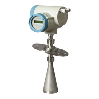
Why does my Siemens Transmitter LR 460 read 100% continuously?
- JJamie GordonAug 31, 2025
If your Siemens Transmitter LR 460 consistently reads 100%, it could be due to a false echo near the antenna. Try moving the LR 460 to a better location, rotating it to change the polarization field, shortening the vessel nozzle to allow the antenna to project into the vessel, or aiming the LR 460 away from the false echo. Another cause could be antenna buildup. In this case, clean the antenna, install a PTFE dust cover, or use the Air Purge option.