Installing/mounting
4.4Measurement setup - Flow
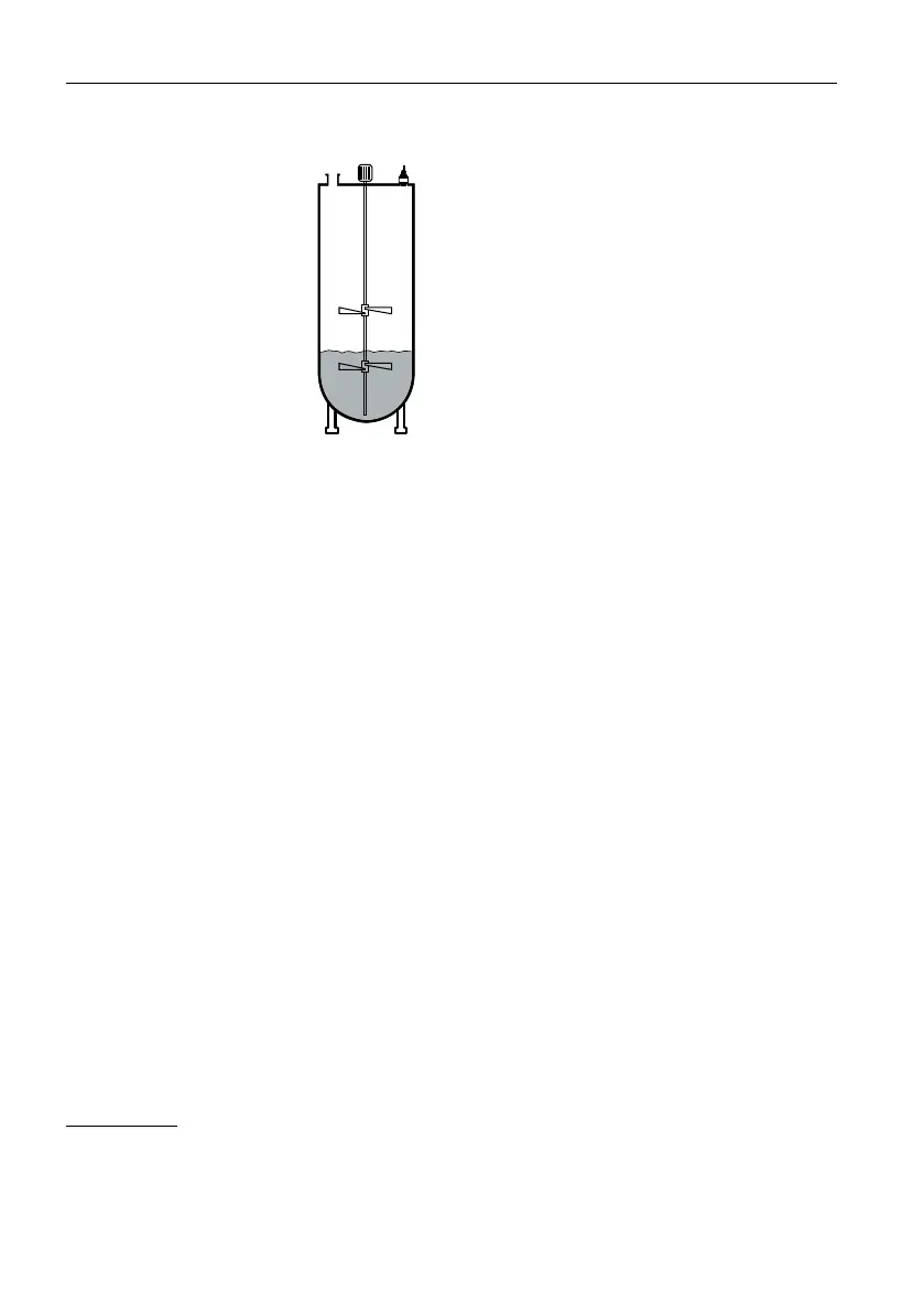
Figure4.8 Agitators
Foam generation
Through the action of filling, stirring and other processes in the vessel, foams which
considerably damp the emitted signals may form on the medium surface.
If foams lead to measurement errors, you should use transmitters with guided radar.
4.4 Measurement setup - Flow
Mounting
In general, the following must be observed while mounting the device:
• Mounting the transmitter on the upstream or inlet side
• Installation in the centre of the flume and vertical to the liquid surface
• Distance to the overfall orifice or Venturi flume
• Distance to the max. height of the orifice or flume for optimum accuracy:
>250mm (9.843in)
1
• Requirements from approvals for flow measurement, e.g. MCERTS
Flume
Predefined curves:
A flow measurement with these standard curves is very easy to set up, as no
dimensional information of the flume is required.
• Palmer-Bowlus flume (Q = kxh
1.86
)
1
The value given takes into account the block distance. At smaller distances, the measuring accuracy is reduced, see ""Technical
data".
SITRANS LR110, HART
Operating Instructions, 10/2023, A5E49829006
17
 Loading...