Do you have a question about the Siemens SM 338 and is the answer not in the manual?
Indicates death, severe personal injury, or property damage if precautions are not taken.
Indicates potential death, severe personal injury, or property damage if precautions are not taken.
Indicates minor personal injury or property damage if precautions are not taken.
Draws attention to particularly important information on the product.
States device use requires qualified personnel.
Emphasizes proper operational procedures.
Compliance with Electromagnetic Compatibility directive.
Specifies products are designed for industrial areas.
Crucial for meeting product requirements.
Guidelines for grounding and shielding installations.
Safety procedure for static discharge.
Details electromagnetic compatibility specifications.
Describes the primary advantages of ultrasonic sensors.
Explains synchronous and asynchronous operation.
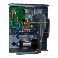
Describes the physical arrangement and connection points of the module.
Explains the function of the DC and SF LEDs.
Explains the magnetostrictive principle used for position encoding.
Details system components, sensor capabilities, and recommendations.
Shows how measuring points are assigned to sensors.
Explains positioning rules and slot usage for the SM 338.
Provides step-by-step instructions for physically installing the module.
Details how to connect the 24V supply to the module terminals.
Discusses wiring, shielding, and grounding for interference-free operation.
Brief introduction to data communication.
Explains communication occurs via the dual port RAM.
Illustrates the structure of the dual port RAM.
Describes how acquired counting values are stored in the input area.
Stores configuration settings for the SM 338 module.
Explains how counters are assigned to sensors and measuring points.
Describes how to set measuring cycle time, start condition, and resolution.
Explains end-of-cycle alarm generation based on cycle time settings.
Describes operation in synchronous mode and its cycle time.
Lists default values for the parameter area after a reset.
Explains the function of the SF LED for system errors.
States the diagnosis area is read-only via the P bus.
Describes system errors occurring at the module level.
Details channel-specific errors and information.
Explains specific error types like parameter error, wire break, etc.
Explains methods for assigning parameters to the SM 338.
Illustrates parameter assignment using SDB 100.
Describes how the module functions and how values are updated.
Explains how the module acquires and stores error information.
Visual representation of the diagnostics process.
Lists detailed technical data, environmental, and storage requirements.
Details the pin assignments for sensor connectors X1 and X2.
Describes the quadruple screw terminal for external power.
Lists recommended accessories like connectors, cables, and shielding.
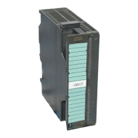
| Product type designation | SM 338 |
|---|---|
| Supply voltage | 24 V DC |
| Weight | 0.5 kg |
| Manufacturer | Siemens |
| Series | SIMATIC S7-300 |
| Operating Temperature | 0°C to 60°C |