Configuring intrusion control units
2
35
Building Technologies A6V10359489_a_en
CPS Fire Safety 30.09.2016
2.5 Configuring a CS440
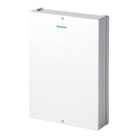
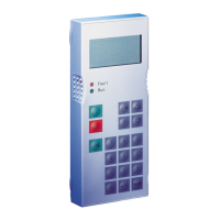
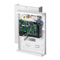
The CS440 is a large intrusion detection system with individual addressing. It
consists of the CS440 control unit and the CT411 operating units. The ADI
addressing elements transmit the detector signals to the control unit.
The structure of the CS440 is divided into logical system levels, and planning and
parameterisation determines its allocation to software and hardware. The logical
system levels include:
l Area (max. 1): Switchover level for the total alarm organisation (UNSET/SET)
of a building or part of a building.
l Sections (max. 99): Operating level for switching ON/OFF a single or several
zones. Within the control unit’s configuration, a section can allocate unlimited
zones.
l Zones (max. 512): Lowest level to which the user has access. Zones must be
allocated to the ADI detector loops. A zone can be a single detector or a group
of detectors. Each zone has its own alarm organisation, and alarm signals are
indicated according to specific zones.
The physical and logical configuration for a CS440 is first defined for the hardware
unit set-up, and then ported to the Composer environment using an export or meta-
file, generated by the CS440 tools.
2.5.1 Configuration checklist
Verify that you have satisfied the items needed in the first checklist before
proceeding to the configuration checklist that follows.
Items needed for configuration
l The number of CS440s in the system.
l The local address (111, 112, etc.) for each unit.
l The metafile generated by the CS440 tool for each unit.
l The connection to the DMS: Cerloop, CDI-Net, or NK8000.
Net/NK8000 requires a serial lin
e available on the gateway.
l Plug-ins needed:
– #350401
ins are installed during the software setup procedure. You can check
that the Plug-ins are actually available using the Composer Plug-in Installer in the
DMS8000 start menu.
Configuration overview
1. Add the folder(s) required for identifying the location of the CS440 in the project
structure tree.
2. Add the CS440 system node to the new folder.
3. Set the CS440 Local Address and Vitality Timer.
4. Import the CS440 metafile.
5. Link the CS440 to the network (Cerloop, CDI-Net, or NK8000).
6. Repeat steps above for all the CS440s in the project.