Configuring intrusion control units
2
25
Building Technologies A6V10359489_a_en
CPS Fire Safety 30.09.2016
– (NK822x only) Subnet, Node, and Logical address for each CS6.
– (NK823x only) Subnet and Node of the CS6.
l The connection to the CS6 network:
– (NK822x only) Connection to Cercom/LON.
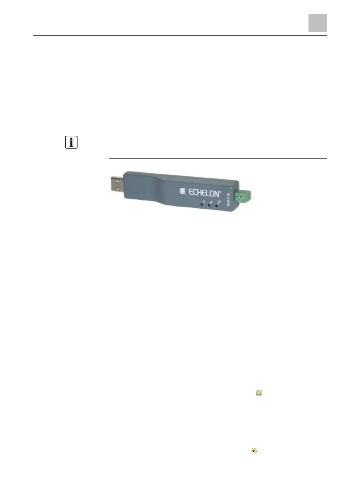
– (NK823x only) Connection via the Echelon U10 USB Network Interface –
TP/FT-10 (to be purchased locally; ECHELON Distributor Partners can be
found on https://www.echelon.com/partners/distributors.htm)
l The NK8000 connection to the DMS.
l (NK822x only) Plug-ins needed:
– #300101
ins are installed during the software setup procedure. You can check
that the Plug-ins are actually available using the Composer Plug-in Installer in the
DMS8000 start menu.
The Echelon U10 USB Network Interface – TP FT10, needed for NK823x
Configuration overview
1. Add the folder(s) required for identifying the location of the CS6 in the project
structure tree.
2. Add the CS6 system node to the new folder.
3. Import the metafile.
4. Add the node needed for the communication with CS6:
– (NK822x only) Add the node for the CerCom/LON bus.
– (NK823x only) Add the node for the USB Port.
5. Link the CS6 to the communication node.
6. Set CerCom/LON bus addresses.
7. (NK822x only) If necessary, configure the remote configuration tunneling.
8. (NK822x only) Repeat the steps above for all the CS6 units in the project.
2.3.2 Configuration procedures
Adding the intrusion system folder
1. In the left-hand bar, click the Generic Template icon .
a A new node is added to the project structure.
2. Select the new folder and name it in the Description field of the Node tab.
Adding the intrusion system node
1. Select the new folder.
2. In the left-hand bar, select the Intrusion folder icon .