Technical Instructions SQM40/41…Actuators
Document No. 7817US
October 6, 2010
8
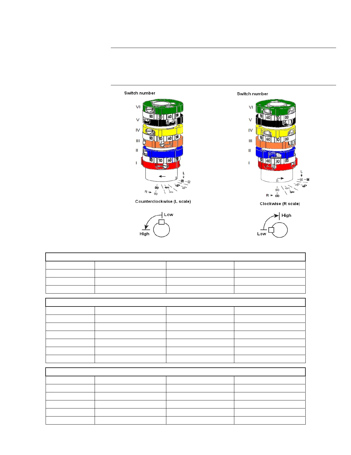
Switches are set via adjusting screws on each cam. Three scales indicate the
angle of switching point (as shown below).
All SQM40/41… actuators have six switch cams but not all models have six
switches. Refer to tables below for details.
SQM4x.x4xxxSC - Modulating
Cam color Switch number Description Factory setting
Red I High 90°
Black V Low 10°
Green VI Ignition 0°
SQM4x.x6xxxSC - 3 position
Cam color Switch number Description Factory setting
Red I High 90°
Blue II Low 0°
Orange III Ignition 10°
Yellow IV Auxiliary switch 30°
Black V Auxiliary switch 30°
Green VI Auxiliary switch 30°
SQM4x.x7xxxSC - 2 position
Cam color Switch number Description Factory setting
Red I High 90°
Blue II Low 0°
Orange III Ignition 10°
Yellow IV Auxiliary switch 30°
Green VI Auxiliary switch 30°
Switch Adjustment
 Loading...