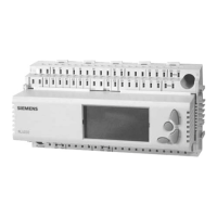
Do you have a question about the Siemens Synco RMU710 and is the answer not in the manual?
Describes the three-level structure of a KNX network: area line, main lines, and lines.
Defines the network address structure (Area.Line.Device) and its components.
Details how device addresses combine with area and line addresses.
Provides points to note when assigning device addresses.
Details the process of designing a KNX network.
Outlines the steps involved in designing a KNX network.
Specifies the maximum number of devices allowed on lines, areas, and networks.
Details decentral bus power supply units (DPSU).
Provides power consumption values for various Synco devices.
Explains central bus power supply units (PSU) and recommendations.
Specifies maximum distances and cable lengths for KNX networks.
Lists key checks for devices, wiring, voltage, and power supply.
Details the process of commissioning using RMZ790/791 operator units.
Guides on starting commissioning with the plant in 'Off' mode.
Explains how to terminate commissioning by setting plant to 'Auto' mode.
Focuses on setting addresses and names for RM controllers.
Provides an overview of the OCI700.1 tool and ACS7... software.
Details addressing devices using the OCI700.1 tool and prerequisites.
Explains manual address assignment for RM controllers using ACS Service.
Details automatic address assignment for devices with problems.
Explains address assignment in programming mode for various devices.
Details setting area and line addresses for line couplers.
Details setting area addresses for area couplers.
Details basic communication settings for RM controllers.
Explains how to set the decentral bus power supply.
Details settings for clock time operation (Master, Slave, Autonomous).
Details how to modify basic settings using ACS Service software.
Explains Synco zoning and lists available zone types.
Details how process values are exchanged using zone addresses in LTE mode.
Details setting zone addresses using RMZ790/791 operator units.
Explains setting zone addresses for RM controllers via operator units.
Covers setting zone addresses using ACS Service.
Explains setting zone addresses for RM controllers via ACS Service.
Explains setting zone addresses for RXB/RXL controllers via ACS Service.
Lists key considerations for designing and commissioning large plants.
Explains how IP routers connect KNX to IP networks.
Covers LTE filtering for couplers and IP routers.
Explains filter settings: Normal (route), Route all, Block all.
Explains IP address assignment via DHCP or manually.
Lists communication errors and their causes.
Lists specific communication errors and fault messages.
Details the H/C changeover function for Synco controllers.
Explains how to combine RM controllers for room control.
Covers lightning protection, overvoltage protection, and EMC.
| Operating voltage | 24 V AC / DC |
|---|---|
| Digital inputs | 6 |
| Analog inputs | 2 |
| Analog outputs | 2 |
| Mounting | DIN rail |
| Product type | Controller |
| Operating Temperature | 0 °C to +45 °C |
| Relative Humidity | 5% to 95% (non-condensing) |
| Display | LCD |
| Usage | Universal controller for heating, ventilation and air conditioning plants |


