TC65 Hardware Interface Description
Strictly confidential / Draft
s
TC65_HD_V00.521 Page 56 of 99 24.05.2005
The VMIC voltage should be filtered if gains larger than 20dB are used. The filter can be
attached as a simple first order RC-network (R
VMIC
and C
F
).
This circuit is well suited if the distance between microphone and module is kept short. Due
to good grounding the microphone can be easily ESD protected as its housing usually
connects to the negative terminal.
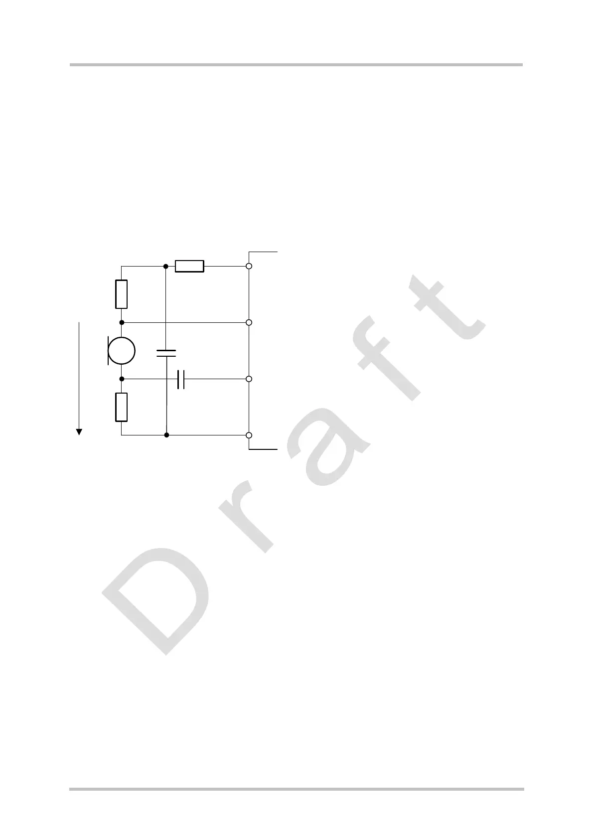
3.13.2.2 Differential Microphone Input
Figure 19 shows a differential solution for connecting an electret microphone.
GSM module
R
A
R
A
V
Bias
C
K
AGND
MICNx
MICPx
VMIC
C
F
R
VMIC
R
A
= typ. 1k
R
VMIC
= 470Ohm
C
K
= typ. 100nF
C
F
= typ. 22µF
V
MIC
= typ. 2.5V
V
bias
= 1.0V … 1.6V, typ. 1.5V
Figure 19: Differential microphone input
The resulting DC voltage between MICPx and AGND should be in the range of 1.0V to 1.6V
to bias the input amplifier. MICNx is automatically self biased to the MICPx DC level. The
resulting AC differential voltage is then amplified in the GSM module.
The VMIC voltage should be filtered if gains larger than 20dB are used. The filter can be
attached as a simple first order RC-network (R
VMIC
and C
F
).
The advantage of this circuit is that it can be used if the application involves longer lines
between microphone and module.