TC65 Hardware Interface Description
Strictly confidential / Draft
s
TC65_HD_V00.521 Page 71 of 99 24.05.2005
5.3 Pin Assignment and Signal Description
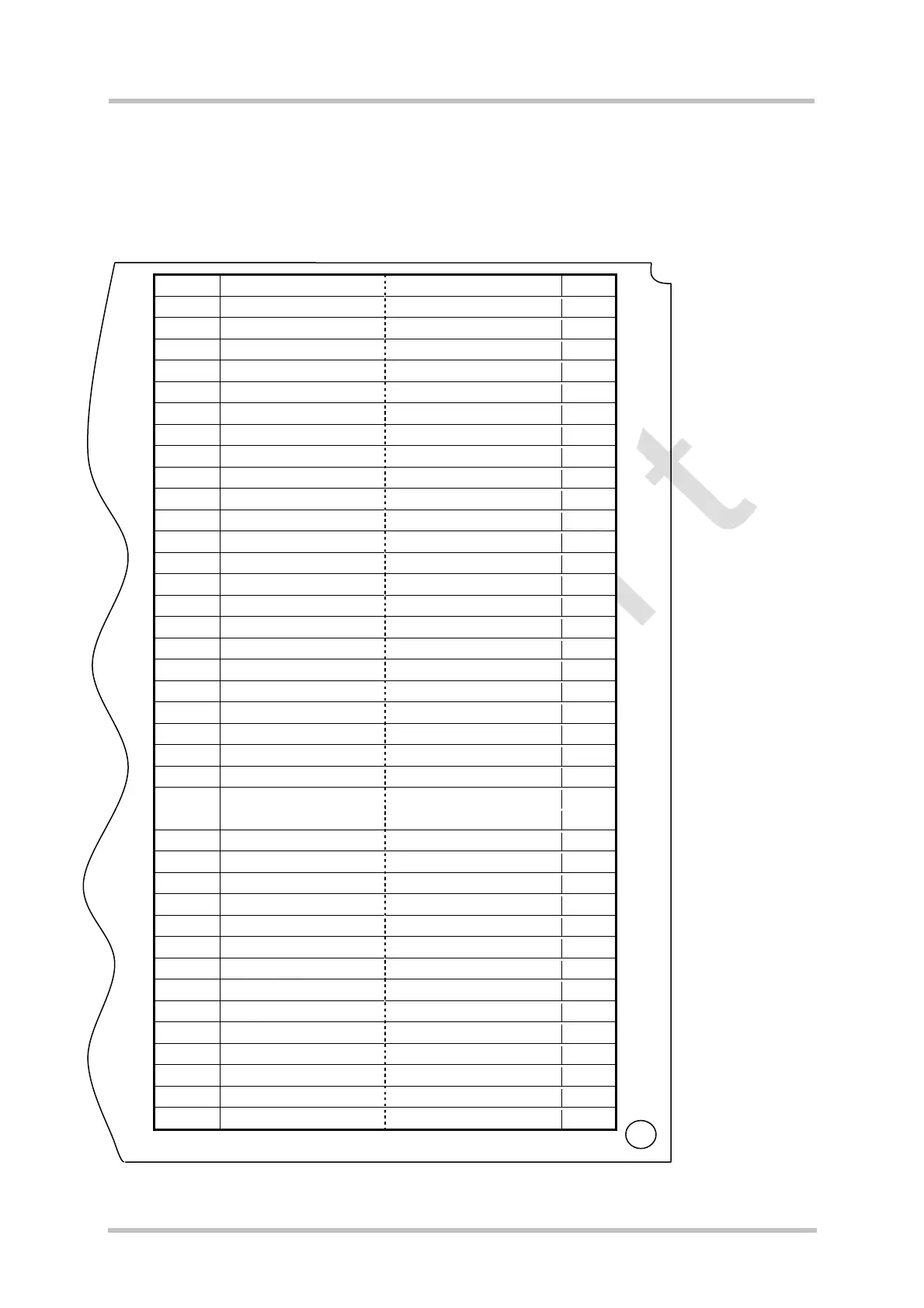
The Molex board-to-board connector on TC65 is an 80-pin double-row receptacle. The
names and the positions of the pins can be seen from Figure 1 which shows the top view of
TC65.
1 GND GND 80
2 ADC1_IN DAC_OUT 79
3 ADC2_IN PWR_IND 78
4 GND
Do not use
77
5 GPIO10 GPIO9 76
6 GPIO8 SPICS 75
7 SPIDI GPIO4 74
8 GPIO7 GPIO3 73
9 GPIO6 GPIO2 72
10 GPIO5 GPIO1 71
11 I2CCLK_SPICLK I2CDAT_SPIDO 70
12 VUSB_IN USB_DP 69
13 DAI5 USB_DN 68
14 ISENSE VSENSE 67
15 DAI6 VMIC 66
16 CCCLK EPN2 65
17 CCVCC EPP2 64
18 CCIO EPP1 63
19 CCRST EPN1 62
20 CCIN MICN2 61
21 CCGND MICP2 60
22 DAI4 MICP1 59
23 DAI3 MICN1 58
24 DAI2 AGND 57
25 DAI1 IGT 56
26 DAI0 EMERG_RST 55
27 BATT_TEMP DCD0 54
28 SYNC CTS1 53
29 RXD1 CTS0 52
30 RXD0 RTS1 51
31 TXD1 DTR0 50
32 TXD0 RTS0 49
33 VDDLP DSR0 48
34 VCHARGE RING0 47
35 CHARGEGATE VEXT 46
36 GND BATT+ 45
37 GND BATT+ 44
38 GND BATT+ 43
39 GND BATT+ 42
40 GND BATT+ 41
Figure 33: Pin assignment (component side of TC65)