TC65 Hardware Interface Description
Strictly confidential / Draft
s
TC65_HD_V00.521 Page 6 of 99 24.05.2005
Figure 23: PCM interface application ..................................................................................... 59
Figure 24: PCM timing............................................................................................................ 60
Figure 25: SYNC signal during transmit burst ........................................................................ 61
Figure 26: LED Circuit (Example)...........................................................................................62
Figure 27: Never use antenna connector and antenna pad at the same time ....................... 64
Figure 28: Restricted area around antenna pad..................................................................... 64
Figure 29: Mechanical dimensions of U.FL-R-SMT connector...............................................66
Figure 30: U.FL-R-SMT connector with U.FL-LP-040 plug ....................................................67
Figure 31: U.FL-R-SMT connector with U.FL-LP-066 plug ....................................................67
Figure 32: Specifications of U.FL-LP-(V)-040(01) plug .......................................................... 68
Figure 33: Pin assignment (component side of TC65) ........................................................... 71
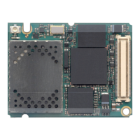
Figure 34: TC65 – top view .................................................................................................... 82
Figure 35: Dimensions of TC65.............................................................................................. 83
Figure 36: Molex board-to-board connector 52991-0808 on TC65 ........................................ 86
Figure 37: Mating board-to-board connector 53748-0808 on application ..............................87
Figure 38: TC65 sample application for Java (draft) .............................................................. 89
Figure 39: Reference equipment for Type Approval .............................................................. 90
Figure 40: Lithium Ion battery from VARTA ...........................................................................98
Figure 41: Lithium Polymer battery from VARTA ................................................................... 99

 Loading...


