9 "SINAMICS V90 PN” Demo Case
9.1 Overview of the demo case
TOs of S7-1500(T)
Entry ID: 109743134, V1.0, 05/2017
Siemens AG 2017 All rights reserved
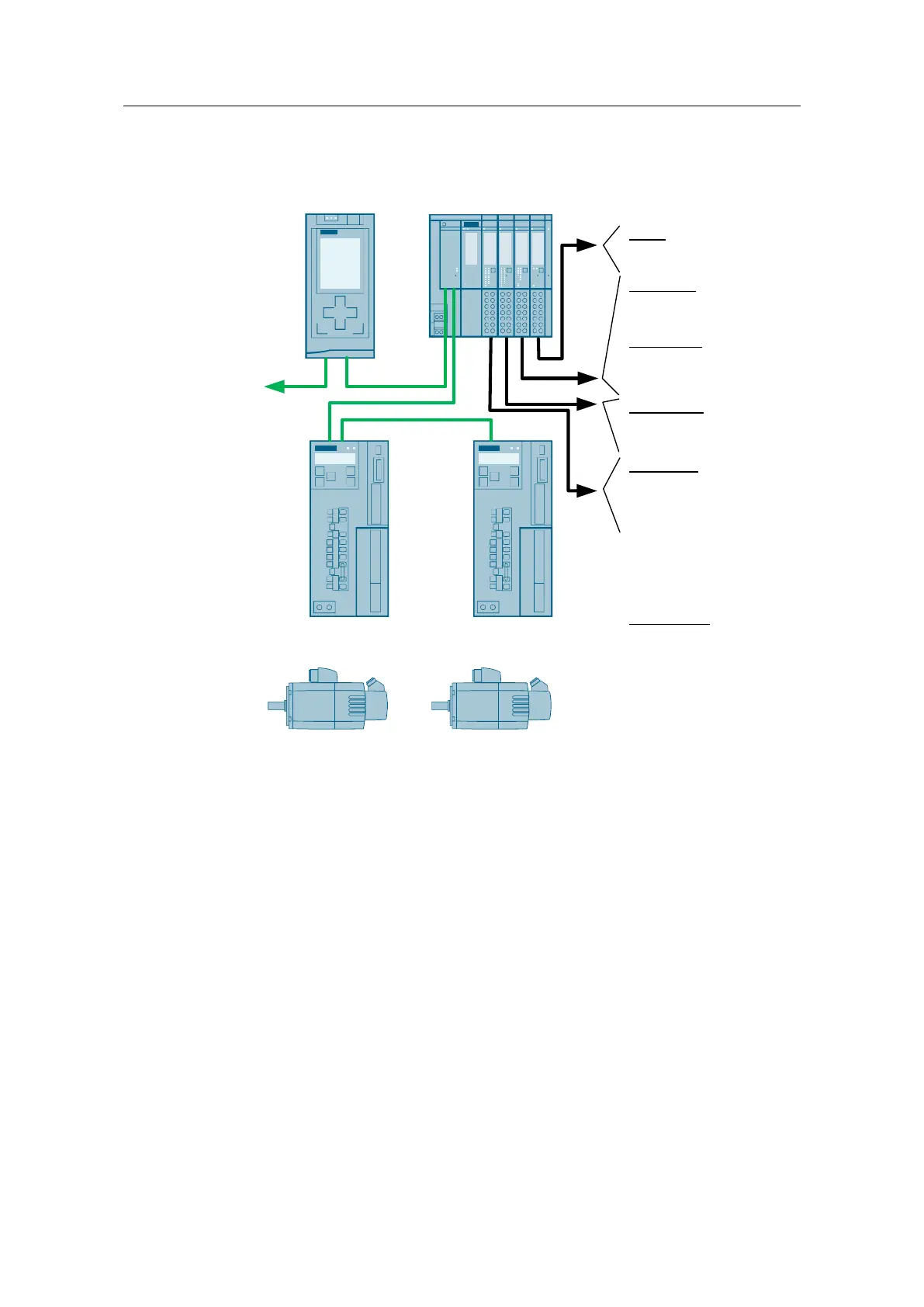
Figure 9-2 Wiring of the "SINAMICS V90 PN” demo case
V90Left
(192.168.0.3)
Name: Drive_1
V90Right
(192.168.0.4)
Name: Drive_2
CPU1515T
(192.168.0.1)
ET200SP
(192.168.0.2)
PG
DQ16x24VDC
00: H0
…
14: H14
TM Timer DI
00: Sensor 0° V90Left
01: Sensor 0° V90Right
02: S15
TM Timer DQ
02: H15
04: LED between Drives
(using Switch „Sync“)
X1P1 X1P2
X1P2X1P1
X150P1 X150P2 X150P1
DI16x24VDC
00: S0
…
14: S14
15: E-Stop
AI 2xU
00: P1
01: P2
Switch „Sync“
DQ4: LED connected to
DQ4 of TM Timer
P24: LED always ON
(using +24V)
9.1.4 Functions
The following functions can be used via the operating elements of the demo case
in interaction with the user program:
Digital inputs via switch (S1…S15)
Digital outputs via LED (H1…H15)
Analog inputs 0…10V (left and right)
Emergency stop directly wired to the drives and switched time-delayed via a
settable delay element (0s...2s)
Measuring input of the TM Timer DIDQ technology module via light barrier
(axes) and toggle switch (S16)
Cam output of the TM Timer DIDQ technology module via LED (H16) and LED
between the axes
 Loading...