Siemens Industry, Inc.
Building Technologies Division
A6V101040156_en--_c4
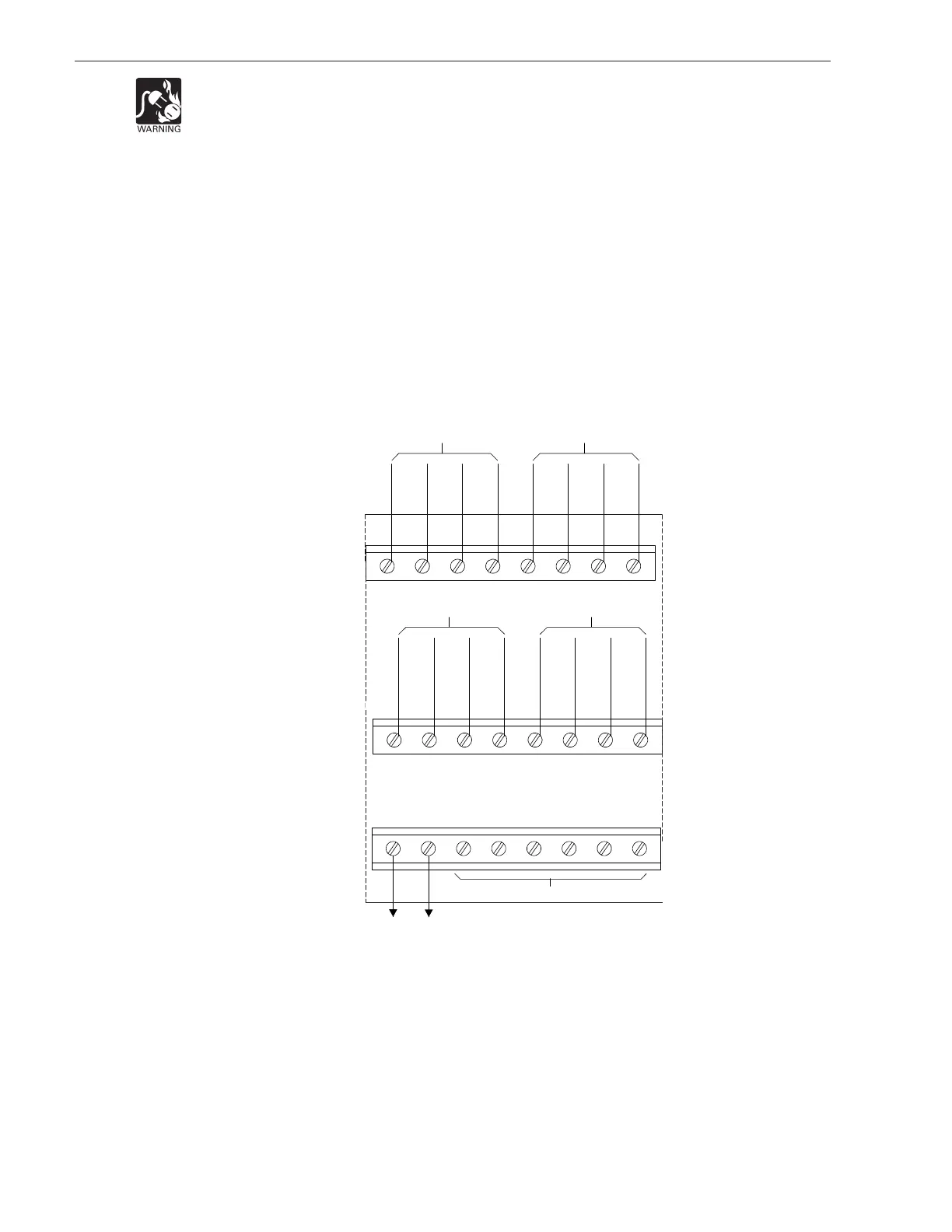
Figure 3
Wiring The 24VDC Power Lines To The XDLC Slot In The CC-5
WIRING
Remove all system power before installation, first battery then AC. (To power up,
connect the AC first, then the battery.)
All field wiring to the XDLC is connected to the terminal blocks of the CC-5 card cage
slot in which it is installed.
To Connect External Wiring
1. Loosen the screw of the terminal by turning it counterclockwise.
2. Insert the wire into the side of the terminal block.
3. Tighten the screw of the terminal block by turning it clockwise.
Connect +24V from the PSC-12 to terminal 17 and -24V from the PSC-12 to terminal
18 of the slot in the CC-5 where the XDLC will be installed. (Refer to Figure 3.)
LINE 1 (OUT)
LINE 1(OUT)
LINE 1 (RETURN)
LINE 1 (RETURN)
LINE 2 (RETURN)
LINE 2 (RETURN)
LINE 2 (OUT)
LINE 2 (OUT)
ZONE 3 ZONE 4
1 2 3 4 5 6 7 8
LINE 1 (OUT)
LINE 1 (OUT)
LINE 1 (RETURN)
LINE 1 (RETURN)
LINE 2 (RETURN)
LINE 2 (RETURN)
LINE 2 (OUT)
LINE 2 (OUT)
ZONE 1 ZONE 2
9 10 11 12 13 14 15 16
ONE SLOT OF CC-5
17 18 19 20 21 22 23 24
24V+
24V-
TO 24VDC FROM THE PSC-12
DO NOT USE
+
-
+++
-
-
-
+
-
+
+
+
--
-