Siemens Industry, Inc.
Building Technologies Division
A6V101040156_en--_c9
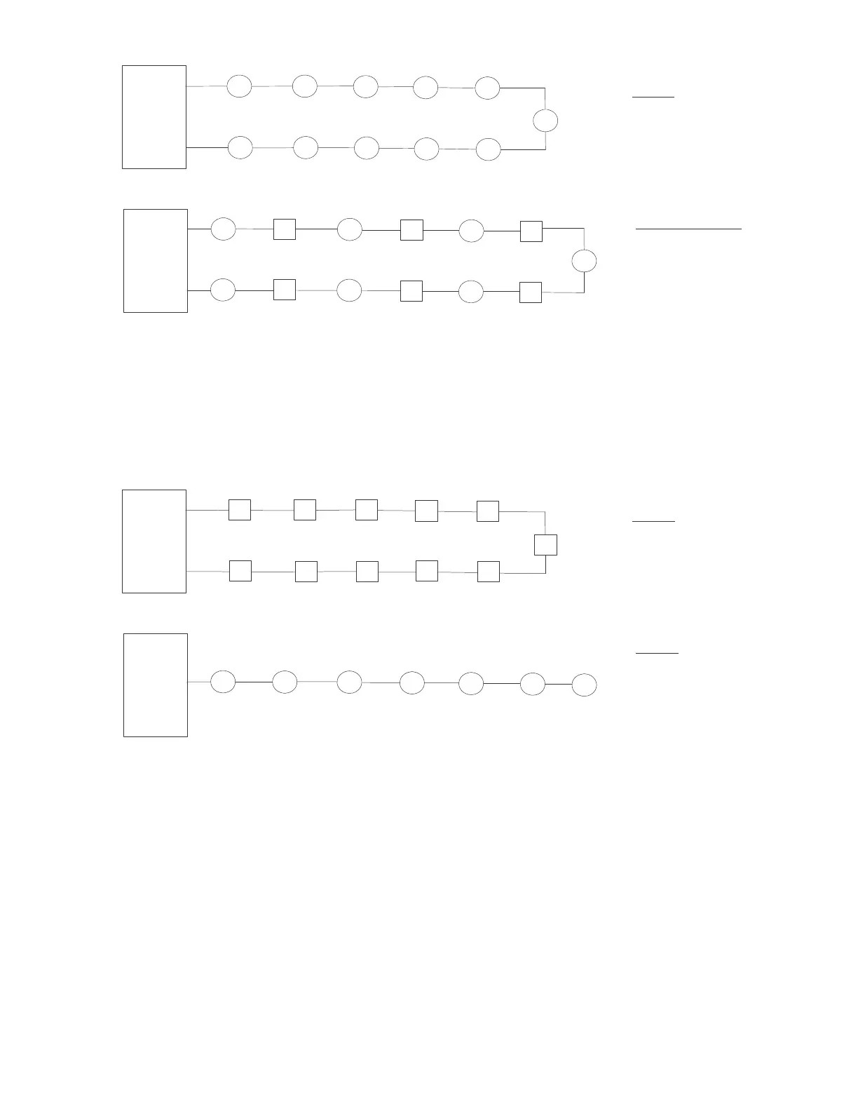
PANEL
XDLC
Out
Return
PANEL
XDLC
Out
Return
PP
PP
P
P
P
P
P
P
P
P
P
P
I
I
I
P
P
P
I
I
I
P
CLASS A
P = Device(s)
(Polarity Insensitive)
No Devices used as Isolators
CLASS A (Mixed Mode)
P = Device(s)
(Polarity Insensitive)
(Max. 20 Devices between Isolators)
I = Isolator Device(s)
Wired for Isolator Mode
PANEL
XDLC
Out
Return
PANEL
XDLC
Out
P
P
P
P
P
P
P
CLASS X
I = Isolator Device(s)
(All wired for Isolator Mode)
CLASS B
P = Device(s)
(Polarity Insensitive)
No Devices used as Isolators
I
I
I
I
I
I
I
I
I
I
I
Figure 5
Class A Device Loop Topologies
Figure 6
Class X and B Device Loop Topologies

 Loading...

