30
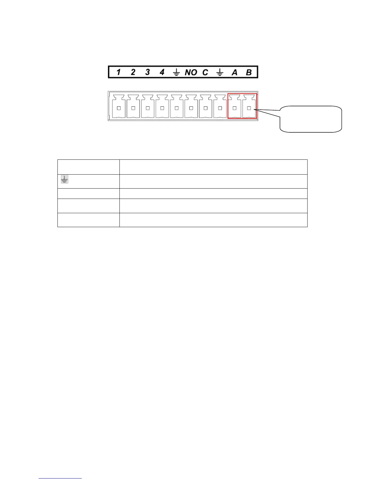
One type of the alarm port is shown as in Figure 3.
Figure 3-6
You can refer to the following sheet for alarm input and output information.
Parameter
Grounding Alarm
Ground line
Alarm Input 1, 2, 3, 4. It becomes valid in low voltage.
NO C One NO activation output.
485 A/B 485 communication port. They are used to control devices such as
PTZ. Please parallel connect 120Ω between A/B cables if there are
AB connection
port