The SIGLENT SDS1000X/SDS1000X+ Series Digital Oscilloscope is a versatile and powerful instrument designed for a wide range of measurement and analysis tasks. This quick start guide provides an overview of its functions, usage, and basic maintenance to help users get started quickly and efficiently.
Function Description
The SDS1000X/SDS1000X+ series oscilloscope is primarily used for observing and analyzing electrical signals. It features multiple trigger types, signal decoding capabilities, and a built-in signal generator (on SDS1000X-S models) to cater to diverse application needs.
Trigger Control: The oscilloscope offers various trigger types to capture specific events in a waveform. These include:
- Edge Trigger: Suitable for general signals, triggering on rising or falling edges.
- Slope Trigger: Triggers when the signal's slope matches a specified condition.
- Pulse Trigger: Captures pulses that meet specific width or polarity criteria.
- Video Trigger: Supports NTSC/PAL analog video signals and HDTV signals, allowing custom line and field settings.
- Window Trigger: Triggers when a signal enters or exits a defined voltage window.
- Interval Trigger: Triggers based on the time interval between two consecutive rising or falling edges that pass through a trigger level and satisfy a limit range.
- DropOut Trigger: Detects signal dropouts.
- Runt Trigger: Triggers on pulses that pass through one trigger level but fail to pass through another, including positive and negative runt pulses.
- Pattern Trigger: Identifies trigger conditions based on a specified logical combination (AND/OR/NAND/NOR) of two channels, where each channel can be set to High, Low, or Invalid.
- Serial Bus Triggers (I2C/SPI/UART/RS232/CAN/LIN): These advanced triggers allow for decoding and triggering on specific events within serial communication protocols. For I2C, users can trigger on start/stop conditions, restart, no ack, EEPROM, or read/write frames with specific device addresses and data values. For SPI, triggering can be set on MISO or MOSI data with variable data lengths. UART/RS232 triggers can be set on start, stop, checksum errors, or data with variable data widths. CAN triggers can be set on start, remote, ID, ID+DATA, or Error of CAN-H or CAN-L signals. LIN triggers can be set on Start, ID, ID+DATA, or Data+Error.
Vertical Control: This section manages the vertical display of waveforms.
- Vertical Scale: Adjusts the amplitude of the waveform, allowing users to zoom in or out. The knob can switch between "Coarse" and "Fine" adjustment modes.
- Position: Controls the vertical offset of the waveform, moving it up or down on the screen. Pressing the knob resets the offset to zero.
- Analog Input Channels: The oscilloscope features multiple analog input channels, each marked by a distinct color, which corresponds to the waveform color on the screen and the physical input connector. Channels can be turned on or off by pressing their respective buttons.
- Math Function: Provides operations such as adding, subtracting, multiplying, dividing, FFT, integral, differential, and square root to analyze waveforms.
- Reference Waveform (Ref): Enables saving and comparing current waveforms with reference waveforms to identify circuit failures. The SDS1000X supports saving two reference waveforms.
Horizontal Control: This section manages the horizontal display of waveforms.
- Time Base: Sets the time per division, expanding or compressing the waveform horizontally. Pressing the knob enters the Zoom mode.
- Roll Mode: Quickly enters the Roll mode for continuous waveform display.
- Position: Adjusts the trigger delay, moving the waveform left or right. Pressing the knob resets the delay to zero.
Run Control:
- Auto Setup: Automatically adjusts horizontal time base, vertical scale, and trigger mode to display the waveform in a perfect state.
- Run/Stop: Toggles the instrument's state between "RUN" (yellow indicator) and "STOP" (red indicator).
Universal Knob: This multi-purpose knob is used for:
- Intensity Adjustment: In non-menu mode, it adjusts waveform intensity and grid brightness/transparency.
- Menu Navigation: In menu mode, it selects submenus and modifies parameters or inputs filenames.
Function Menus: The oscilloscope features several dedicated function menus:
- Cursors: Opens the cursor function for manual and track cursor modes.
- Acquire: Sets acquisition mode (Normal/Peak-Detect/Average/ERes), interpolation mode (Sinx/X or linear), and memory depth. Also enables XY function and sequence function.
- Save/Recall: Manages saving and recalling files, including setups, waveforms, pictures, and CSV data.
- WaveGen (SDS1000X-S only): Opens the signal generator menu, offering ten types of signals (Sine, Square, Ramp, Pulse, DC, Noise, Cardiac, Gaus Pulse, Exp Rise, ExpFall) with a maximum output frequency of 25MHz (SineWave). Users can also download and output four custom waveforms using EasyWave software.
- Measure: Accesses measurement settings for type, statistic function, all measure, and gate measure. Up to five parameters can be selected. Statistic functions display current, mean, min, max, Std-Dev, and count.
- Display/Persist: Enters the display menu to set grid, intensity, brightness, and transparency, and quickly enables the persist function.
- Default: Resets the oscilloscope to its default setup (1V/div and 1µS/div).
- Clear Sweeps: Clears measurement statistics and persist display.
- History: Records up to 80,000 frame waves. If sequence function is enabled, it records only the specified frames (up to 1024 frames).
- Decode: An optional function for decoding serial bus protocols (I2C, SPI, UART/RS232, CAN, LIN) for up to two analog signals.
- Digital (SDS1000X+ only): An optional function for opening the digital channel menu, supporting 16 digital channels.
- Utility: Configures system functions and parameters such as IO settings, sound, language, Pass/Fail, Self Cal, option installation, and updates.
Usage Features
Quick Start Procedure:
- Inspect Shipping Container: Retain packaging if damaged until contents are checked.
- Inspect Instrument: Contact SIGLENT if damaged or defective.
- Check Accessories: Verify against the packing list; contact SIGLENT for missing or damaged items.
- Adjust Supporting Legs: Tilt the oscilloscope for stable placement and easier viewing.
- Connect to AC Power Supply: Use the provided power cord to connect to a 100-240V, 50/60/440Hz AC power source.
- Power-on Inspection: Turn on the power switch. The instrument performs self-tests, and the user interface displays upon completion.
- Connect the Probe: Connect the BNC terminal of the probe to a channel BNC connector on the front panel. Connect the probe tip to the test circuit point and the ground alligator clip to the circuit's ground terminal.
- Function Inspection: Press "Default" to reset, connect the probe's ground clip to the Ground Terminal, and the probe tip to the Compensation Signal Output Terminal. Press "Auto Setup" to display a square waveform.
- Probe Compensation: Properly compensate the probe upon first use to ensure accurate measurements. Adjust the low-frequency compensation adjustment hole on the probe until a correct square waveform is displayed.
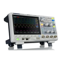
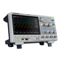
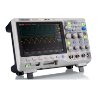
Front Panel Overview: The front panel includes the user interface, universal knob, function menus, WaveGen, decode control, digital function control, Run/Stop, Auto Setup, trigger control, horizontal control, channel vertical control, probe compensation, analog channel inputs, shortcut of save, digital channel inputs, USB host, and power on/off button.
Rear Panel Overview: The rear panel features a handle for carrying, a LAN interface for remote control, a USB device port for SCPI commands, Pass/Fail or Trig Out Output, an AWG output terminal (SDS1000X-S only), a safety lock hole, and an AC power socket.
User Interface Elements:
- Product Logo: SIGLENT trademark.
- Channel Label/Waveform: Different colors for channels and their corresponding waveforms.
- Working State: Indicates Arm, Ready, Trig'd, Stop, or Auto.
- Horizontal Time Base: Displays time per grid, adjustable from 2ns to 50s.
- Trigger Position: Displays the trigger position on the waveform.
- Frequency Counter: Displays the frequency of the current waveform.
- Sample Rate/Memory Depth: Displays current sample rate and memory depth.
- Trigger Setting: Shows trigger source, coupling mode, trigger level, and trigger type/condition.
- Channel Setting: Displays probe attenuation factor, channel coupling mode, voltage scale, BW limit status, and impedance.
- Trigger Level Position: Displays the vertical position of the trigger level.
- I/O Connection Status: Icons indicate USB Host, USB Device, and LAN port connection status.
- Menu: Displays softkeys for the currently selected function module.
Using Security Lock: The instrument can be secured using a security lock by aligning it with the lock hole, plugging it in, turning the key clockwise, and removing the key.
Maintenance Features
General Care and Cleaning:
- Storage: Avoid direct sunshine, fog, liquid, or solvent exposure.
- Cleaning Procedure:
- Disconnect from all power sources.
- Clean with a soft, wet cloth.
- Remove loose dust with a soft cloth.
- Be careful not to scratch the LCD during cleaning.
- Notice: Do not use corrosive liquids or chemical cleansers.
- Ensure the instrument is completely dry before restarting to prevent short circuits or injuries.
Troubleshooting: The manual provides solutions for common issues:
- Dark Screen After Power On: Check power connection, switch, fuse (contact SIGLENT for replacement), and restart.
- No Waveform Displaying After Sampling: Check probe connection to signal cord and BNC, probe connection to item under test, signal generation from item under test, and resample.
- Incorrect Voltage Amplitude Measurement: Verify probe attenuation coefficient matches the channel's attenuation ratio.
- Unstable Waveform Display: Check trigger source, waveform correctness (time base), trigger type (Edge for general, Video for video), and trigger holdoff setting.
- No Display After Pressing Run/Stop: Check trigger mode (Normal/Single) and trigger level. Set to middle or change to Auto mode. "Auto Scale" can automatically adjust these settings.
- Ladder-like Waveform Display: Increase horizontal time base for better resolution. Change "Type" in "DISPLAY" from "Vectors" to "Dots" if lines between sample points cause the issue.
- USB Storage Not Recognized: Check USB flash disk functionality, USB Device Host functionality, ensure the USB disk is flash type (not hardware type), verify FAT32 format, restart the instrument and reinsert USB. Contact SIGLENT if issues persist.
Safety Precautions:
- Proper Power Line: Use only the specified power cord.
- Grounding: Ensure the instrument is correctly grounded through the protective earth conductor before connecting input/output terminals.
- Signal Wire Connection: Do not connect signal wires to high voltage as their potential is equal to earth.
- Terminal Ratings: Review all terminal ratings and instructions to prevent fire or electric shock.
- Overvoltage Protection: Avoid overvoltage (e.g., from thunderstorms) to prevent electrical shock.
- Electrostatic Prevention: Operate in an ESD-protective area, grounding conductors before connection.
- Ventilation: Maintain adequate ventilation to prevent overheating and damage. Regularly inspect intake and fan.
- Exposed Circuits/Components: Do not touch exposed parts when power is on.
- Fuse: Use only the specified fuse.
- Covers: Do not operate the instrument with covers or panels removed.