Do you have a question about the SIGLENT SDS1202X and is the answer not in the manual?
Provides a summary of essential safety precautions to prevent injury or damage to the instrument.
Explains the meaning of warning terms and symbols used in the manual and on the product.
Instructions for inspecting the shipping container and instrument for damage upon receipt.
Steps to perform a basic function inspection of the oscilloscope's operation.
Instructions for compensating the oscilloscope probes for accurate measurements.
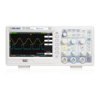
Explains the main elements and layout of the oscilloscope's user interface.
Procedure for adjusting the horizontal time base (Time/division).
How to adjust the trigger delay of the waveform display.
How to select the trigger source (CH1, CH2, EXT, AC Line).
Explanation of available trigger modes: Auto, Normal, and Single.
Procedure for setting the trigger level to detect specific signal events.
Setting trigger coupling modes (DC, AC, LF Reject, HF Reject).
How to use trigger holdoff to stabilize triggering on complex waveforms.
Enabling noise rejection to improve trigger stability in noisy environments.
Overview of available trigger types for signal analysis.
Setting up triggers and decoding for IIC serial bus signals.
Setting up triggers and decoding for SPI serial bus signals.
Setting up triggers and decoding for UART/RS232 serial bus signals.
Configuring waveform types and their parameters (frequency, amplitude, etc.).
Procedure for sending arbitrary waveforms to the oscilloscope.
Selecting the output load impedance for the waveform generator.
Performing self-calibration for the Arbitrary Waveform Generator.
Troubleshooting steps for a dark or blank screen after power on.
Steps to resolve issues where no signal waveform is displayed.
Diagnosing why measured voltage amplitude differs from the actual value.
Troubleshooting steps for waveforms that are not stable.
Resolving issues where the display shows nothing after pressing Run/Stop.
Solutions for waveform display appearing as a ladder or staircase.
Troubleshooting USB connection problems between PC and oscilloscope.
Steps to resolve problems with the oscilloscope not recognizing USB storage devices.
| Bandwidth | 200 MHz |
|---|---|
| Sample Rate | 1 GSa/s |
| Channels | 2 |
| Memory Depth | 14 Mpts |
| Display | 7 inch TFT-LCD (800x480) |
| Waveform Capture Rate | 100, 000 wfm/s |
| Vertical Resolution | 8 bits |
| Input Coupling | DC, AC, GND |
| Operating Temperature | 0 °C to +50 °C |
| Weight | 2.6 kg |
| Interfaces | USB Host, USB Device, LAN, Pass/Fail, Trigger Out |
| Trigger Types | Edge, Pulse, Video |
| Timebase Range | 2 ns/div to 50 s/div |